User interface for blood treatment device

a technology for treating devices and user interfaces, which is applied in the field of user interfaces for blood treatment devices, can solve problems such as language barriers, non-english speaking operators having difficulty with english language messages, and still not intuitive to less-trained operators of rrt devices

Inactive Publication Date: 2005-08-02
GAMBRO LUNDIA AB
View PDF36 Cites 163 Cited by
  • Summary
  • Abstract
  • Description
  • Claims
  • Application Information

AI Technical Summary

Benefits of technology

[0019]Another aspect of the proposed method is that it assists the operator in detecting tubes that are not properly inserted into sensor elements of the RRT device console. Voltage outputs from sensors, such as a photometric blood leak detector and an ultrasonic air detector, can be used to detect fluid tubes that are not properly inserted into the sensor or other components of the RRT device. The user attention of the operator will be attracted by the flashing element of the pictogram so that user could insert the tube into the sensor tubing receptacle. The pictorial element will immediately stop flashing if the condition is corrected.

Problems solved by technology

This plain language alarm message methodology is effective, but is still not intuitive to less-trained operators of the RRT device.
Also, in the global marketplace, confusion often results from a language barrier and non-English speaking operators have difficulty with English language messages.
Although these icons help a user of a dialysis device navigate through a menu system, they are not helpful in troubleshooting faults in the blood fluid path of the device.
However, the graphics user interfaces disclosed in the prior art lack the ability to clearly direct a user to the specific point in the blood fluid path where an occlusion has been detected or the blood flow continuity has been broken.

Method used


Image

  • User interface for blood treatment device
  • User interface for blood treatment device
  • User interface for blood treatment device

Examples


Embodiment Construction

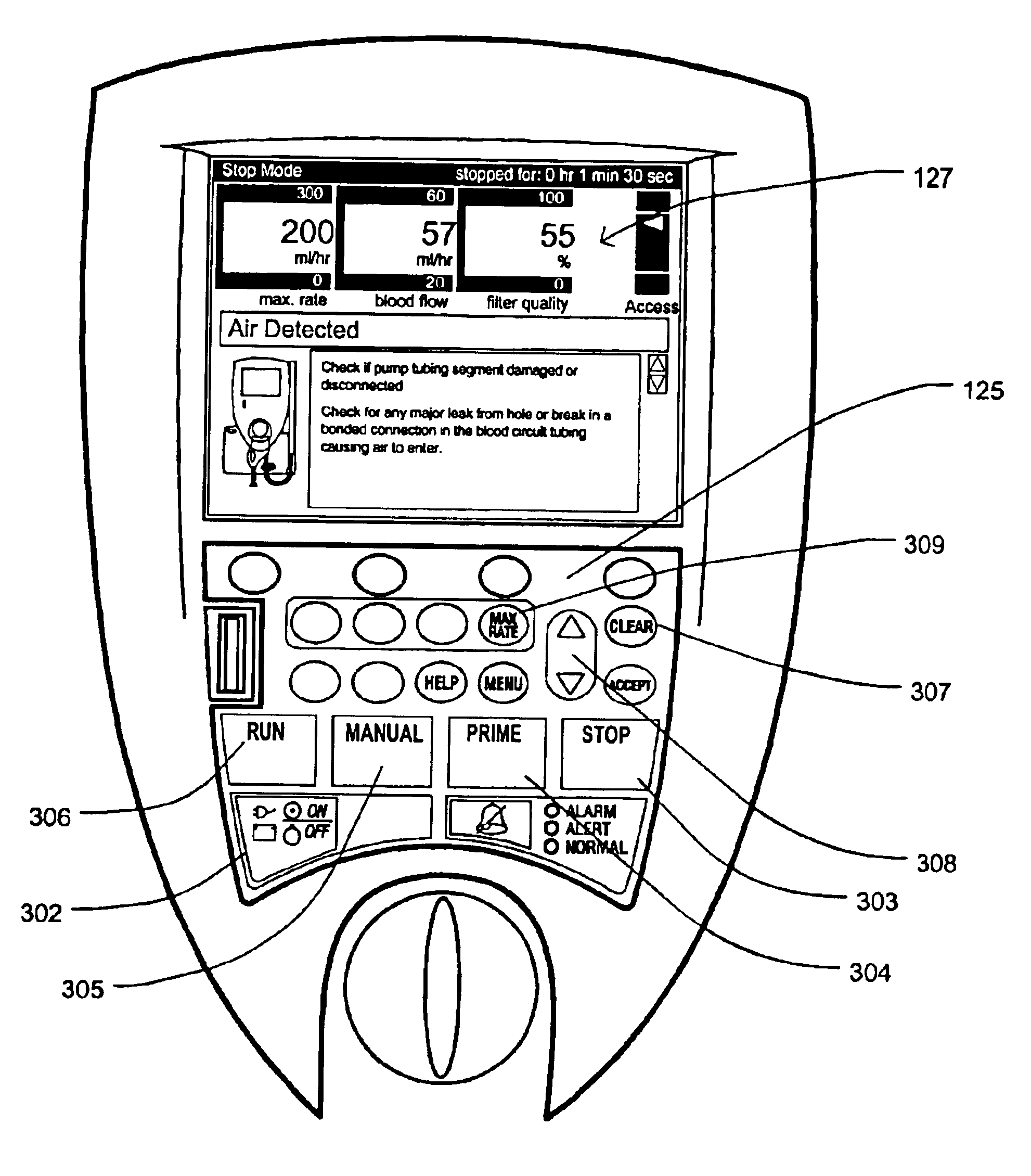
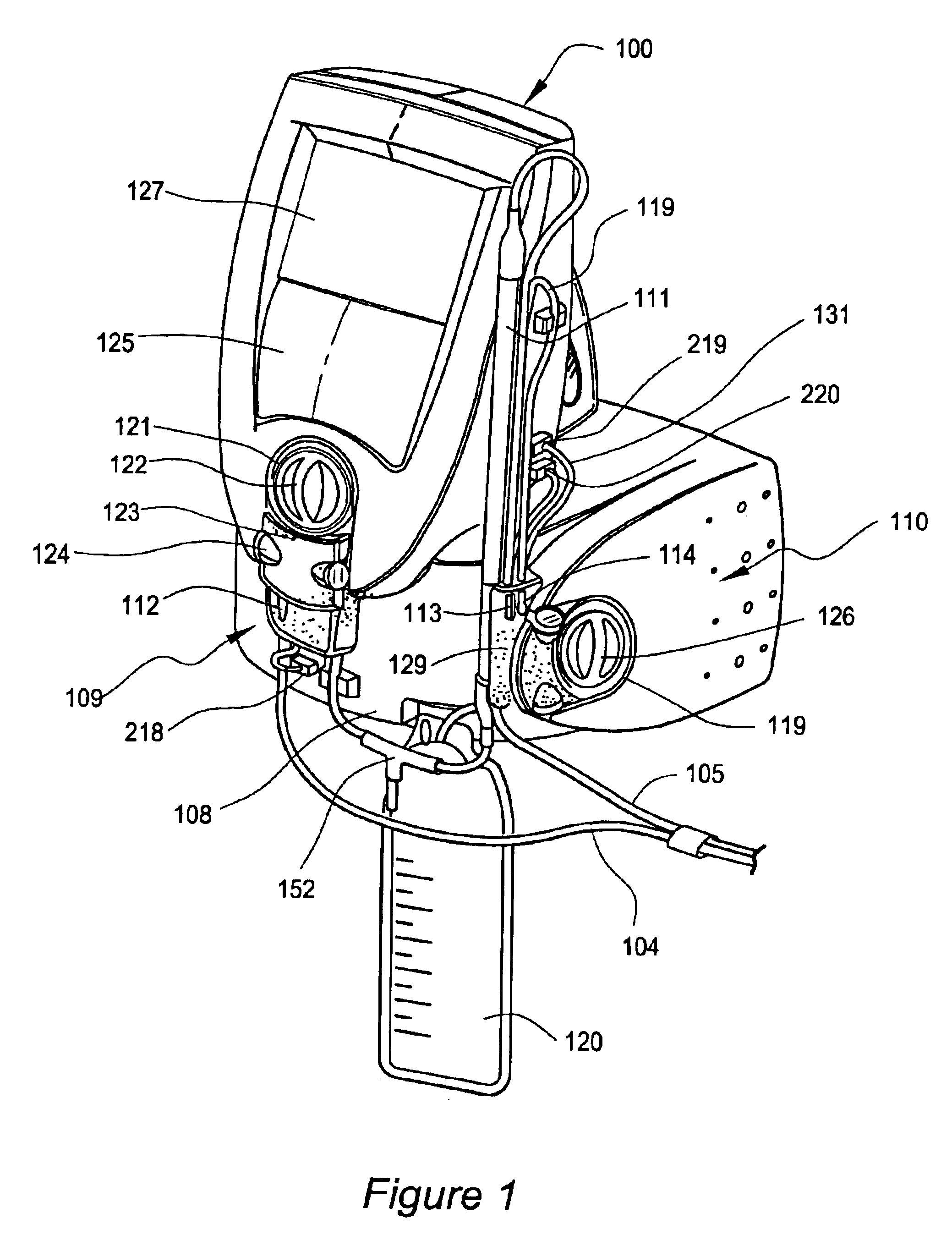
[0032]The preferred embodiment of the present invention is a Graphical User Interface (GUI) that is a part of a blood ultrafiltration system and is used with a single use disposable set for ultrafiltration of blood to treat fluid overload in patients in a hospital setting. The disposable ultrafiltration set and the system are disclosed in commonly-owned U.S. patent application Ser. No. 09 / 660,195 filed on Sep. 12, 2000 and U.S. patent application Ser. No. 09 / 696,642 filed on Oct. 26, 2000, which applications are incorporated herein by reference.

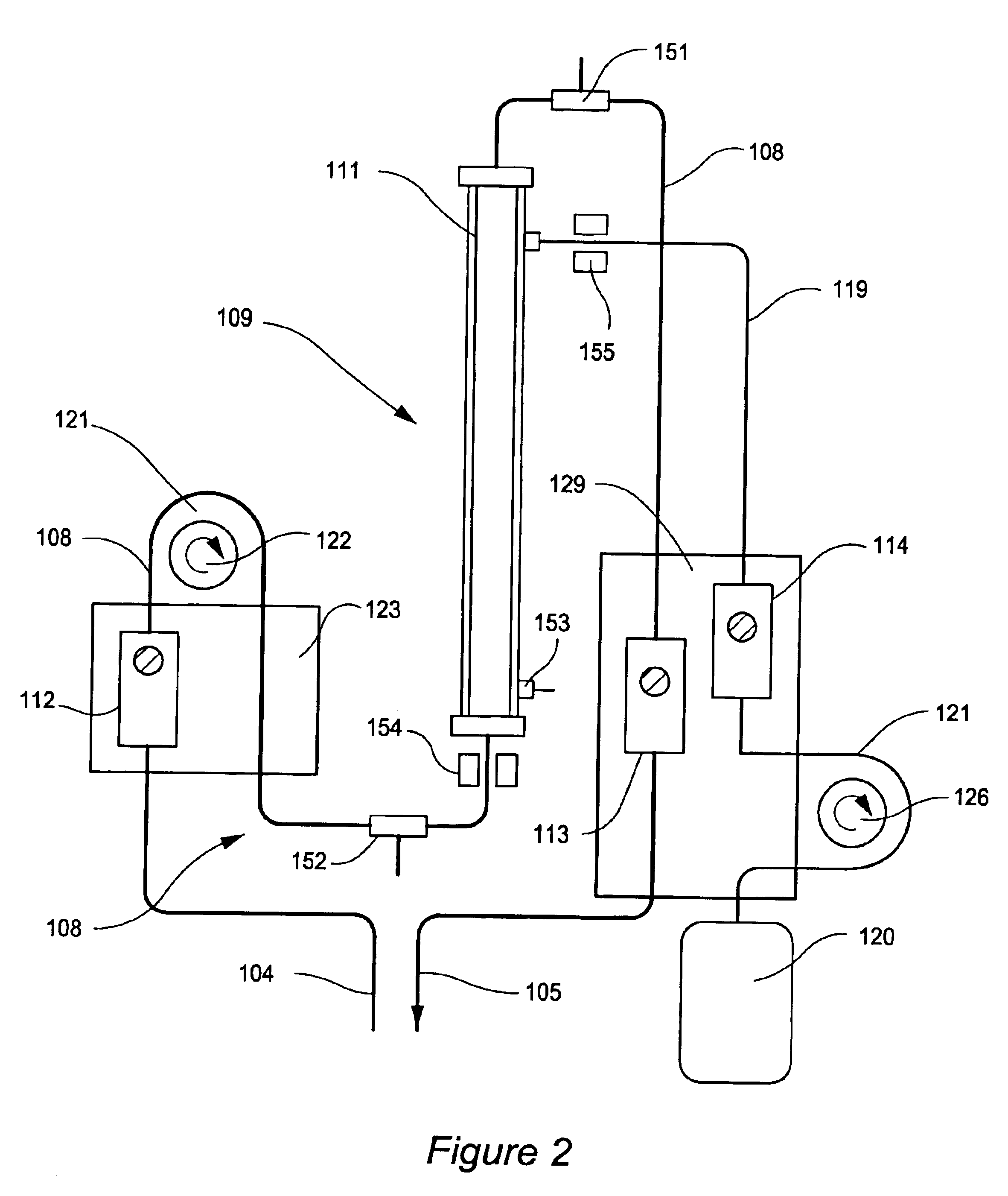
[0033]To remove excess fluid from the patient the ultrafiltration set is mountable on a system console that is equipped with two pumps. One pump moves and controls the flow rate of blood through the tubing and filter of the ultrafiltration set. The other pump moves and controls the flow rate of ultrafiltrate. The ultrafiltration set contains a disposable blood / ultrafiltrate fluids circuit with an integral blood separation filter and three int...


PUM

PropertyMeasurementUnit
pressureaaaaaaaaaa
pressureaaaaaaaaaa
colorsaaaaaaaaaa

Abstract

A graphical user interface for a medical instruments for a Renal Replacement Therapy includes a pictogram representation of cthe fluid path of an extracorporeal blood circuit that represents fluid lines, pumps and sensors. To assist the user in responding to alarms and rectifying faults in the system the source of a potential trouble is animated. The location of a trouble spot is easily identified by flashing of the corresponding element of the pictogram, change of color or thickness of a corresponding line.

Description

FIELD OF THE INVENTION[0001]This application is a divisional of and claims priority to application Ser. No. 09 / 833,798 filed Apr. 13, 2001, and now U.S. Pat. No. 6,773,412. This invention relates to the medical instruments for extracorporeal treatment of blood and user interfaces for such instruments. One embodiment of the invention relates to a user interface for medical instruments for Renal Replacement Therapy and Artificial Kidney therapies.BACKGROUND OF THE INVENTION[0002]1. Renal Replacement Therapies[0003]Renal Replacement Therapy (RRT) can be performed in specialized dialysis centers for treatment of chronic patients that have permanently lost kidney function and in hospitals for treatment of patients with a need for temporary replacement of renal function. Different modalities of Continuous Renal Replacement Therapy (CRRT) have been used to treat patients suffering from excess fluid overload and acute renal failure. In acute settings, CRRT has been performed using standard ...

Claims


Application Information

Patent Timeline
Patent Type & Authority Patents(United States)
IPC IPC(8): A61M1/16
CPCA61M1/16A61M1/1692A61M1/3639A61M2205/14A61M2205/15A61M2205/502Y10S706/924A61M2205/18A61M2205/3331A61M2205/3344A61M2205/3375A61M2205/50A61M1/3403A61M1/341A61M1/3607A61M1/3609A61M1/3641G16H20/40G16H40/63A61M1/3401A61M1/362264A61M1/36224A61M1/36222A61M1/36225G16H50/20
Inventor O'MAHONY, JOHN J.HALPERT, ANDREWGELFAND, MARK
Owner GAMBRO LUNDIA AB
Why Eureka
Try Eureka