Ultrasonically actuated needle pump system

a technology of ultrasonically actuated needles and pump systems, which is applied in the field of micromechanical systems and ultrasonically actuated instruments, can solve the problems of complication, incident tissue damage becomes particularly a problem, and the use of such needles is accompanied by tissue damage, so as to achieve efficient pumping of body fluids

Inactive Publication Date: 2005-08-02
WISCONSIN ALUMNI RES FOUND
View PDF29 Cites 13 Cited by
  • Summary
  • Abstract
  • Description
  • Claims
  • Application Information

AI Technical Summary

Benefits of technology

[0007]In accordance with the present invention, an ultrasonically actuated needle pump system provides efficient pumping of body fluids with minimal disruption of body tissue adjacent to the needle. Ultrasonic pumping action occurs through the needle system without interference with the pumping action by the skin or other body tissue which is penetrated. The needle system is well-suited to the extraction of precisely controlled amounts of fluid for purposes such as sampling of interstitial fluid.
[0008]The needle pump system of the invention includes an outer, stationary tubular needle having a distal end, which may have a penetrating tip, and a hollow bore. An inner tubular needle is mounted in the bore of the outer needle. The inner and outer needles may be formed as any type of elongated hollow structure acting as a conduit for fluid, and may have any desired cross-sectional shape in addition to the common round inner and outer surfaces for such conduits. The distal end of the inner tubular needle is located adjacent to, at or spaced slightly away from, the distal end of the outer needle. An ultrasonic actuator is coupled to the inner tubular needle at a position away from the distal end to selectively drive the inner needle in longitudinal mode vibrations at ultrasonic frequencies. The inner needle is free to vibrate independently of the outer needle, and the outer needle is not vibrated and is essentially stationary. The outer needle may, for example, be formed of metal in a conventional fashion with a sharp, penetrating tip, and the inner tubular needle may be formed of a capillary tube which may be formed of a transparent material, such as glass, which facilitates inspection of the contents of the inner needle as it is pumped therethrough. It is found that, in accordance with the invention, the vibration of the inner tubular needle results in highly efficient pumping of fluid from the distal end of the needle system, e.g., at the penetrating tip of the outer needle, to the proximal end opening of the inner tubular needle. Such pumping action occurs when the distal end of the needle system is inserted into a sample of liquid by itself as well as when the needle system is used to penetrate skin tissue. Because the outer needle is stationary, it does not mechanically disrupt or heat the adjacent body tissue, and the surrounding outer needle shields the vibrating inner needle from contact with body tissue so that no damping of the vibrations of the inner needle occurs.
[0009]It is also found in accordance with the invention that the needle system of the invention may be utilized to pump fluid from a container at the distal end and to efficiently atomize the liquid at an open proximal end of the inner needle.

Problems solved by technology

While conventional hypodermic needles that can be manipulated by hand by medical personnel have been successfully used for many years for withdrawing relatively large samples of blood and other body fluids, the use of such needles is, of course, accompanied by some tissue damage as the needle punctures the skin and subdermal tissues of the subject.
This incidental tissue damage becomes particularly a problem if repeated sampling is required, for example, for monitoring of blood sugars by diabetics or in other situations where it is desirable to be able to closely monitor the levels of blood components or drug levels within a patient.
The small size of the needles and the small amounts of interstitial fluids that are withdrawn through the needle complicate the problem of drawing fluids through the needle to a sample container or a sample chamber.
A limitation of the use of such ultrasonically actuated needles for body fluid sampling is the potential damping of the vibration of the needle as it is inserted into relatively stiff skin tissue.
The damping of the vibrations of the needle by skin tissue reduces the efficiency of pumping of fluid from the needle.
Further, increasing the amplitude of the vibrations applied to the needle to overcome the loss of efficiency may result in excessive disruption of the body tissue penetrated by the needle by virtue of the mechanical displacement, cavitation, and localized heating of tissue caused by the vibrations.

Method used


Image

  • Ultrasonically actuated needle pump system
  • Ultrasonically actuated needle pump system
  • Ultrasonically actuated needle pump system

Examples


Embodiment Construction

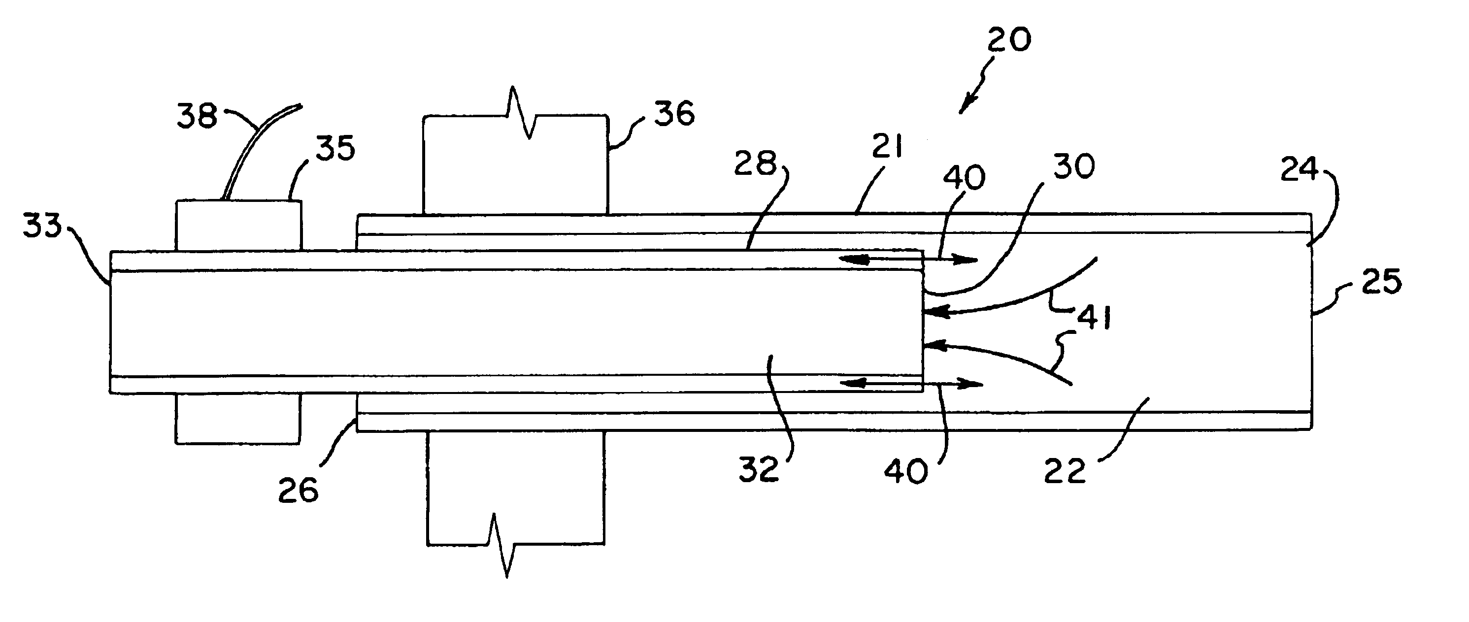
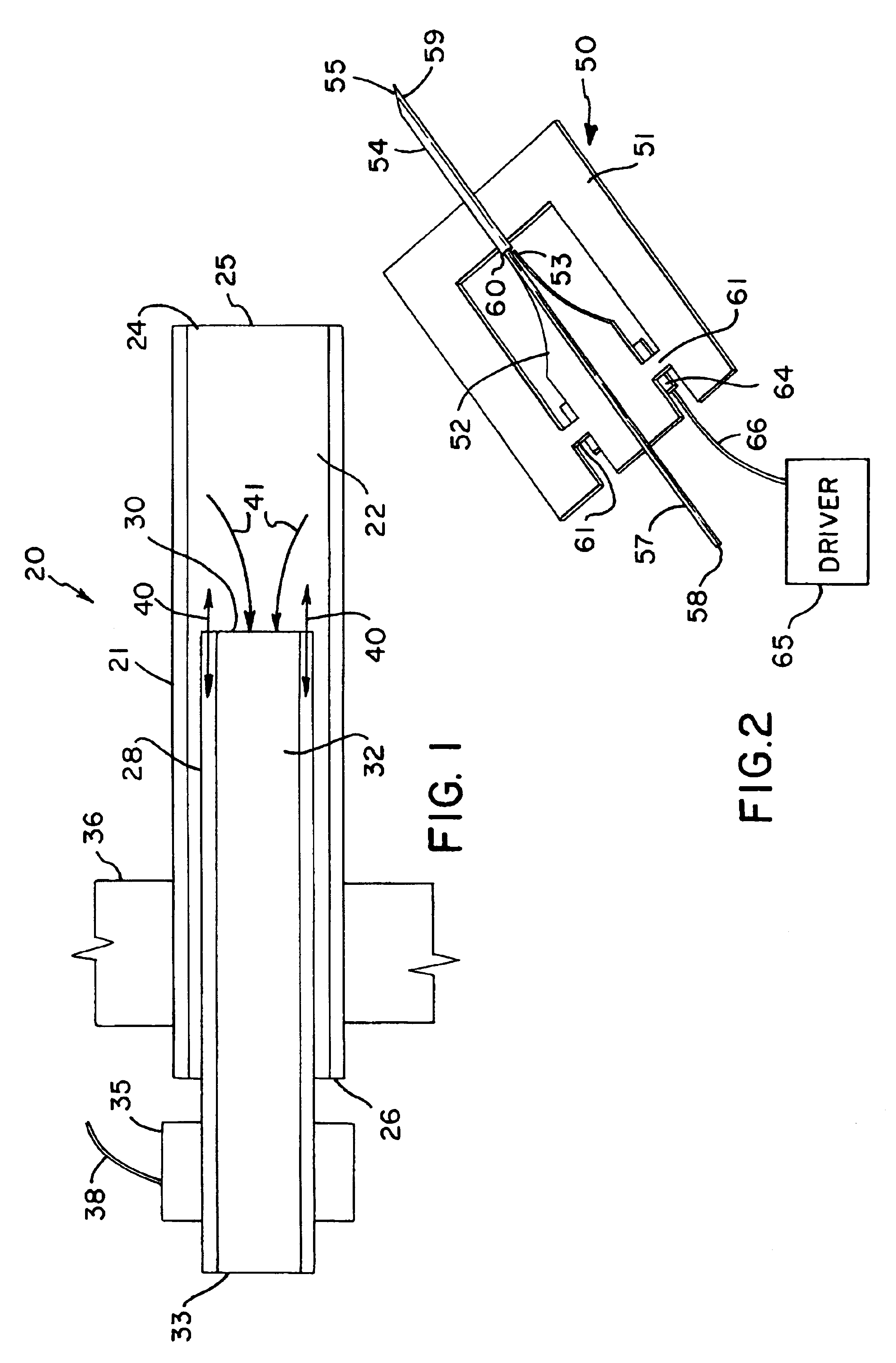
[0024]A simplified cross-sectional view of an ultrasonically actuated needle pump for fluid sampling or atomization in accordance with the invention is shown generally at 20 in FIG. 1. The ultrasonic pump includes an outer tubular needle 21 having an inner bore 22, which may be circular as shown, a distal end 24 which has an end opening 25 that may be formed blunt as shown (or the opening may be cut on a bias to form a penetrating tip), and a proximal end 26. A tubular inner needle 28 is mounted within the bore 22 of the outer needle 21 and is not secured to the surfaces of the bore 22 so that it can move longitudinally without substantial interference from the outer tubular needle 21. The inner tubular needle 28 has a distal end 30 which, as shown in FIG. 1, is adjacent to but preferably spaced from the distal end 24 of the outer tubular needle 21. Preferably, the distal end 30 of the inner needle is spaced from the distal end 24 of the outer needle by a distance in the range of a ...


PUM


Abstract

An ultrasonically driven pump, which may be used for sampling body fluids or atomizing liquids, has a stationary outer needle and an inner needle mounted within the bore of the outer needle. The distal end of the inner needle is positioned adjacent to the distal end of the outer needle. The inner needle is ultrasonically vibrated by an ultrasonic actuator without vibrating the outer needle, with resulting draw of liquid through the distal end of the outer needle into the bore of the inner needle for discharge through the proximal end of the inner needle. The outer needle can be formed to have a penetrating tip suited for penetrating the skin of a subject to allow sampling of body fluids including interstitial fluids. The pump can also be used for atomizing liquid, by drawing liquid from a supply that is pumped from the distal end to an open proximal end of the inner needle where the liquid is discharged by atomization into the atmosphere.

Description

CROSS-REFERENCE TO RELATED APPLICATION[0001]This application is a divisional of application Ser. No. 09 / 617,478, filed Jul. 17, 2000, now U.S. Pat. No. 6,638,249, issued Oct. 28, 2003, the disclosure of which is incorporated herein by reference.STATEMENT OF GOVERNMENT RIGHTS[0002]This invention was made with United States government support awarded by the following agencies: NSF 9632527. The United States government has certain rights in this invention.FIELD OF THE INVENTION[0003]This invention pertains generally to the field of surgical instruments and similar devices, to micromechanical systems, and to ultrasonically actuated instruments.BACKGROUND OF THE INVENTION[0004]Various types of hypodermic needles have been developed for the injection of substances, e.g., drugs, into the body, or the withdrawal of body fluid samples, e.g., blood. For drawing blood samples from a vein, the subject's blood pressure may be sufficient to pump the blood sample through the bore of the hypodermic...

Claims


Application Information

Patent Timeline
Patent Type & Authority Patents(United States)
IPC IPC(8): A61B5/15A61B17/00A61B10/00A61M37/00
CPCA61B5/1411A61B5/14514A61B2010/008A61B2017/00765A61M37/0092A61B5/150022A61B5/150083A61B5/150297A61B5/150389A61B5/150503A61B5/150946A61B5/150977A61B5/15142
Inventor LAL, AMITLEE, CHUNG-HOON
Owner WISCONSIN ALUMNI RES FOUND
Why Eureka
Try Eureka