Engine welder with shielding gas generation

a shielding gas and engine technology, applied in welding/cutting media/materials, manufacturing tools, welding apparatus, etc., can solve the problems of increasing the weight of the gas cylinder, affecting the operation of the welder, so as to reduce the air pollution during operation, facilitate and facilitate operation, and facilitate the effect of setting up and/or transportation

Inactive Publication Date: 2005-08-02
LINCOLN GLOBAL INC
View PDF13 Cites 10 Cited by
  • Summary
  • Abstract
  • Description
  • Claims
  • Application Information

AI Technical Summary

Benefits of technology

[0013]The primary object of the present invention is the provision of an arc welding system and method which forms a high quality weld bead between two metal plates by an gas shielded arc welding procedure.
[0015]Still another and / or alternative object of the present invention is the provision of an arc welding system and method which reduces air pollution during operation.
[0017]Still yet another and / or alternative object of the present invention is to provide an arc welder that is more convenient and easier to operate.
[0018]A further and / or alternative object of the present invention is to provide an engine welder which is easier to set up and / or transport to various locations.

Problems solved by technology

Arc welders that are designed to receive power from an electric outlet are limited to use in a location that has an electric outlet which is rated to supply the needed current for operation of the arc welder.
As a result, the weight of the gas cylinder increases the difficulty in moving an engine welder that has the gas container connected thereto.
For the smaller welding units, the transport of the heavy gas container poses its own difficulties when being transported to the welding site.
The requirement that a particular welding operation require shielding gas can also pose problems when the gas in the container is exhausted.
The replacement of the gas container is both difficult and time consuming.

Method used


Image

  • Engine welder with shielding gas generation
  • Engine welder with shielding gas generation
  • Engine welder with shielding gas generation

Examples


Embodiment Construction

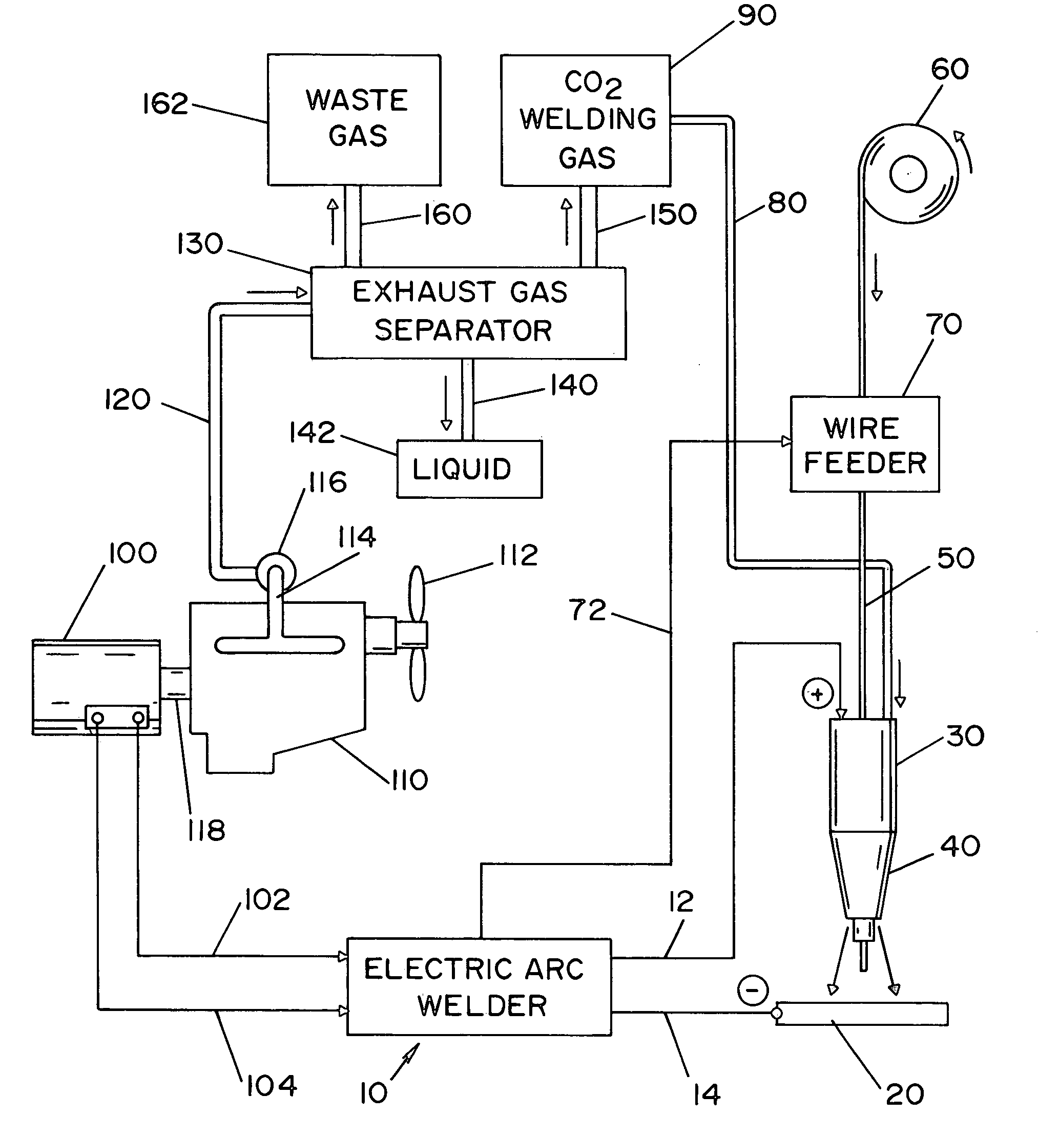
[0028]Referring now to the drawings wherein the showings are for the purpose of illustrating preferred embodiments of the invention only and not for the purpose of limiting the same, FIG. 1 illustrates an electric arc welder 10 for welding together a workpiece 20. The arc welder 10 is connected to a welding gun, not shown, that includes a welding head 30. The electric arc welder 10 directs a current wave form to the welding nozzle 40 and workpiece 20 via positive and negative electrical connections 12, 14, respectively. The welding head 30 includes a nozzle 40 that facilitates in directing a consumable electrode 50 toward workpiece 20. The consumable electrode can be a solid wire electrode, a cored electrode, a coated electrode, etc. If the consumable electrode is a cored and / or coated electrode, the consumable electrode can include alloy agents and / or fluxing agents. The consumable electrode 50 is unwound from wire roll 60 and is fed to the welding gun and through the welding head ...


PUM

PropertyMeasurementUnit
currentaaaaaaaaaa
poweraaaaaaaaaa
weight percentaaaaaaaaaa

Abstract

A liquid and gas separator to generate a shielding gas from the exhaust gas of an internal combustion engine. The liquid and gas separator can be a separate portable component or a component that is integrated with the arc welder.

Description

INCORPORATION BY REFERENCE[0001]The present invention incorporates the use of engine welders of the general type described in U.S. Pat. Nos. 6,296,027 and 6,172,332, United States Patent Application Publication No. 2003 / 155,339 published on Aug. 21, 2003 entitled “ScrewAir Compressor for a Welder”, and U.S. patent application Ser. No. 10 / 390,436 filed Mar. 17, 2003 entitled “Self-Contained Integrated Welder / Generator and Compressor.”[0002]The invention relates to the art of welding with an electric arc and more particularly to an arc welder that is at least partially supplied a shielding gas from a source other than a shielding gas cylinder and even more particularly to an arc welder that is at least partially powered by an engine welder and the exhaust from the engine welder is at least partially used as a shielding gas.BACKGROUND OF THE INVENTION[0003]Arc welders are typically powered by plugging the arc welding machine into an electrical outlet or having the arc welder equipped w...

Claims


Application Information

Patent Timeline
Patent Type & Authority Patents(United States)
IPC IPC(8): B23K9/173B23K9/16B23K9/32B23K35/38
CPCB23K9/164B23K9/324B23K35/38
Inventor STAVA, ELLIOTT K.
Owner LINCOLN GLOBAL INC
Why Eureka
Try Eureka