Laser plasma generation method and structure thereof

a plasma and plasma technology, applied in the direction of active medium materials, nuclear reactors, greenhouse gas reduction, etc., can solve the problems of metal debris emission from the nozzle, insufficient divergence angle in practice, and insufficient density of target molecules to obtain the required x-ray intensity, so as to avoid bending of the target jet and sufficient plasma compression and heating

Inactive Publication Date: 2005-08-02
MOCHIZUKI TAKAYASU
View PDF9 Cites 17 Cited by
  • Summary
  • Abstract
  • Description
  • Claims
  • Application Information

AI Technical Summary

Benefits of technology

[0022]In the present invention, in order to obtain sufficient compression and heating of the plasma during two-dimensional focusing of the jet tube target, it is desired that the target is irradiated by several laser beams as uniformly as possible from different directions whose angle separations are equal in the plane normal to the target axis. This is also desirable in order to avoid a bending of the target jet which will be caused by unbalanced laser ablative acceleration.

Problems solved by technology

But this causes erosion of the nozzle metal surface, resulting in emission of metal debris from the nozzle.
But the divergence angle does not become small enough in practice.
For example, when the laser focus spot is placed 10 mm down the nozzle exit, the ejected flow is in a state of spray so that the density of the target molecules is not high enough to obtain a required x-ray intensity.
However, there are serious problems regarding stabilities in their size and trajectories.
According to their report, a diameter of the liquid Xe jet flow is limited in less than 40 μm because of evacuation capacity of their vacuum pump and likely because of hydrodynamic instability, and the position of the focus spot needs to be confined only in the range of continuous liquid flow.
On the other hand, the hydrodynamic energy carried by shockwaves, compression waves etc. is dissipated in the target, causing the debris emission and / or massive evaporation in the surrounding target material.
However, it is not easy to control their sizes, trajectories, velocities and repetition rate in a stable manner.
Furthermore it is doubtful to use droplet targets at a high repetition rate operation because a high velocity and a precise timing of the droplets are required as above described
But, in addition to the difficulty in supplying the cavities at a fast rate the x-ray flux emitted from the outlet hole of the cavity is much limited by the size of the hole.

Method used


Image

  • Laser plasma generation method and structure thereof
  • Laser plasma generation method and structure thereof
  • Laser plasma generation method and structure thereof

Examples

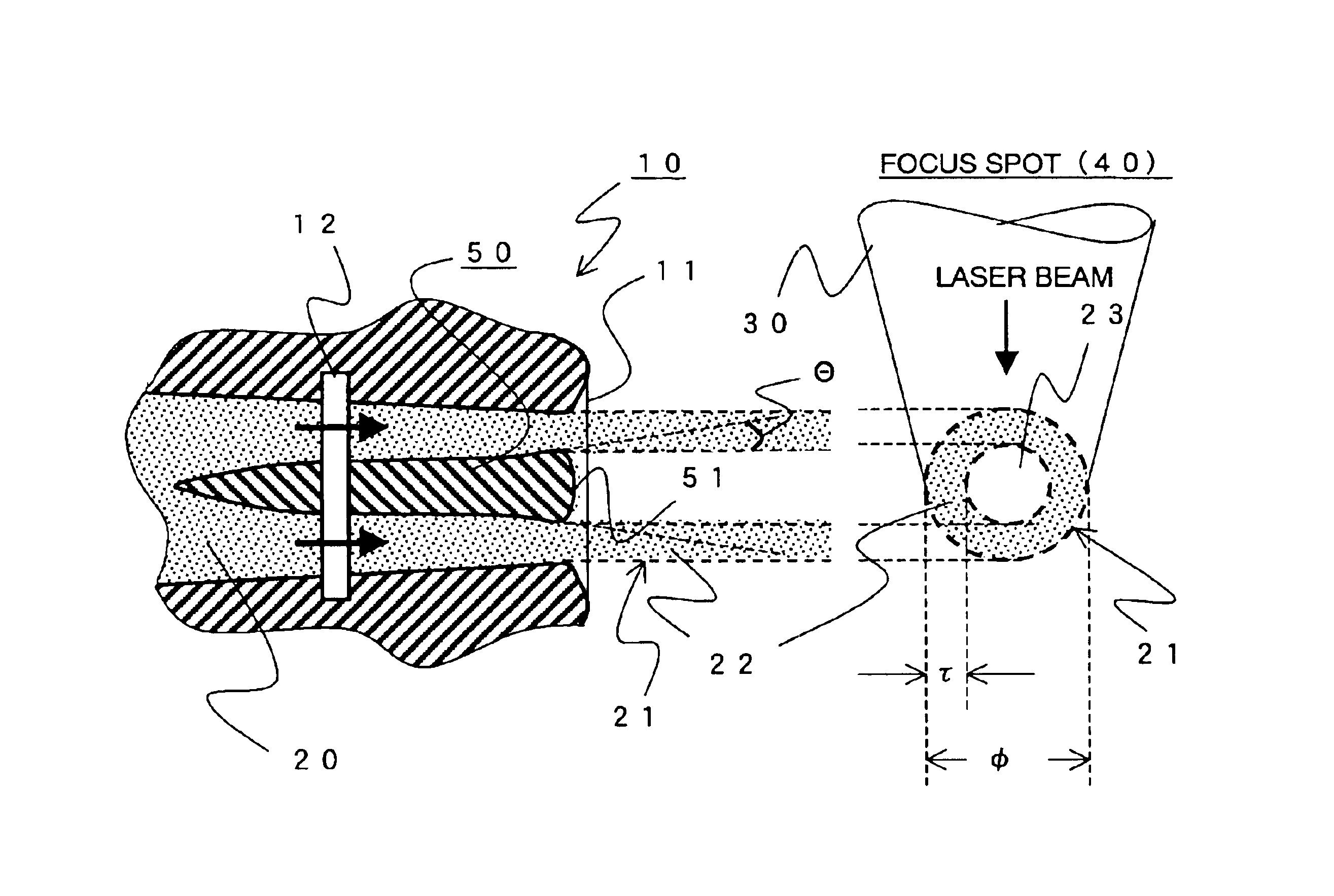
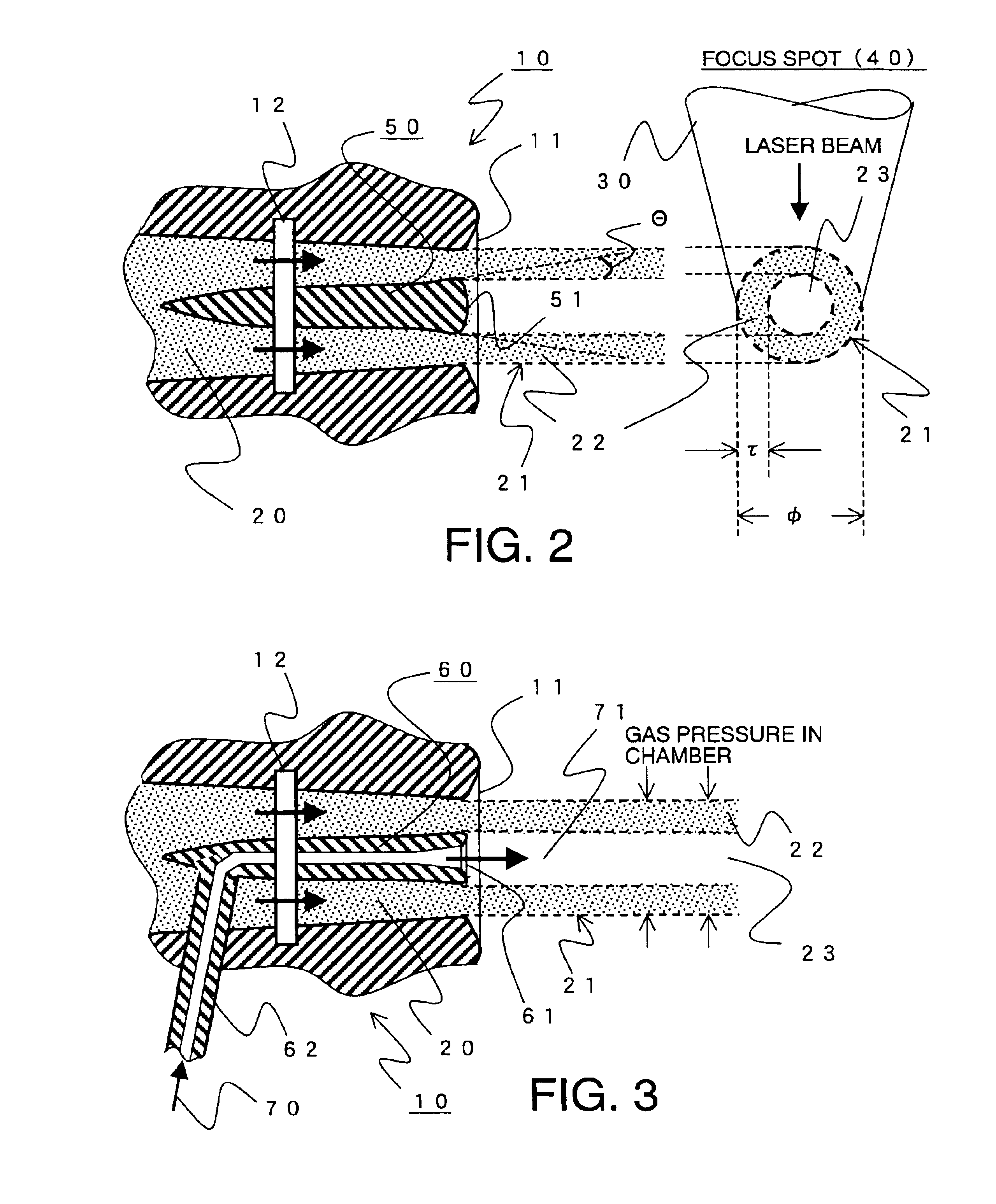

Embodiment Construction

[0033]Now, embodiments of the present invention will be described referring to figures. The figures used are only for illustration to explain the present invention so that the dimensions including sizes of components and configurations are partially exaggerated, thus not accurate.

[0034]And the jet tube target with a hollow shell may be a flow of solid state material which has been solidified immediately after it was ejected from the nozzle opening. But, for convenience we assume that the jet tube target is in a cylindrical column which is of a most effective shape in the embodiments described hereunder.

[0035]FIG. 2 is a block diagram of function for describing one embodiment according to the present invention.

[0036]In the laser plasma generation method illustrated in FIG. 2, a jet tube target 21 is formed by ejecting a target material 20 of liquid state and / or half solid state, for example of high viscosity, from a nozzle 10 inside a vacuum chamber. Then by focusing and irradiating ...


PUM


Abstract

In laser-plasma generation, a fluid of target material is jet out to form a jet tube target 21 having a diameter φ and a wall thickness τ with a shell and a hollow space within the shell by using a core-column. A plurality of pulse-like laser beams 30 are directed to the jet tube target radially and equiangularly-spaced directions and are simultaneously focused and irradiated onto the jet tube target to generate the plasma.

Description

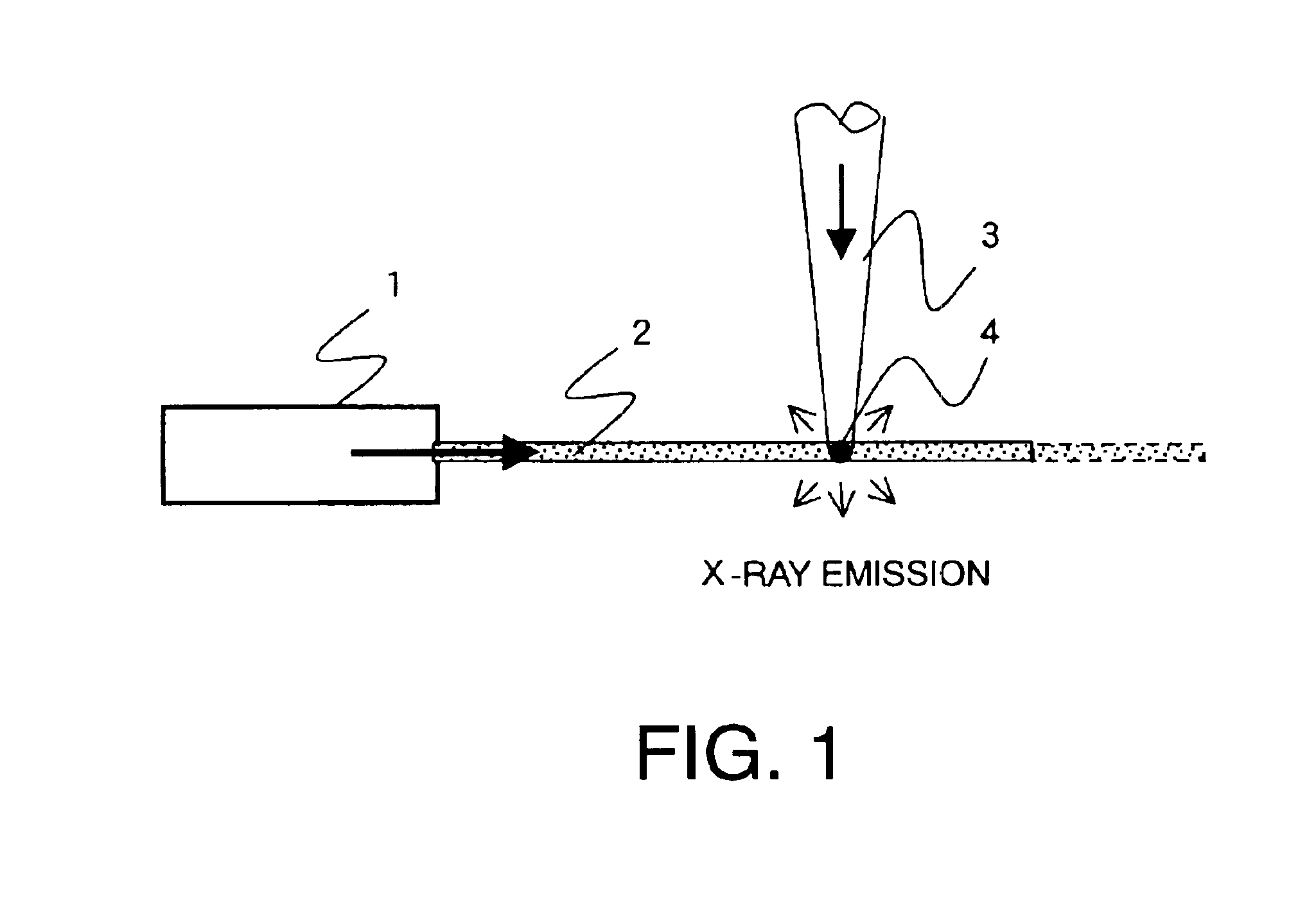
[0001]This application claims priority to prior application JP 2002-109587, the disclosure of which is incorporated herein by reference.BACKGROUND OF THE INVENTION[0002]The present invention relates to a laser-plasma generation method and its structure in which a target material that is fluid at least in one of liquid and solid states is ejected from a nozzle to form a column-like jet flow and then irradiated by focused pulsed lasers composed of at least single beam to generate a high-temperature high-density plasma that emits high-average power x-ray which is useful for x-ray material processing, x-ray lithography, and material analysis. In particular, the present invention relates to a laser-plasma generation method and its structure which provides a method that can supply with target continuously at a small gas emission rate, and which can enhance the x-ray conversion efficiency.[0003]The effort has been made to realize a practical laser-plasma x-ray source in order to use x-rays...

Claims


Application Information

Patent Timeline
Patent Type & Authority Patents(United States)
IPC IPC(8): H05H1/22H05H1/02H05G2/00G21K5/08H01L21/027G21K5/02H05H1/24
CPCG21B1/23H05G2/003H05G2/008H05G2/006Y02E30/10
Inventor MOCHIZUKI, TAKAYASU
Owner MOCHIZUKI TAKAYASU
Why Eureka
Try Eureka