

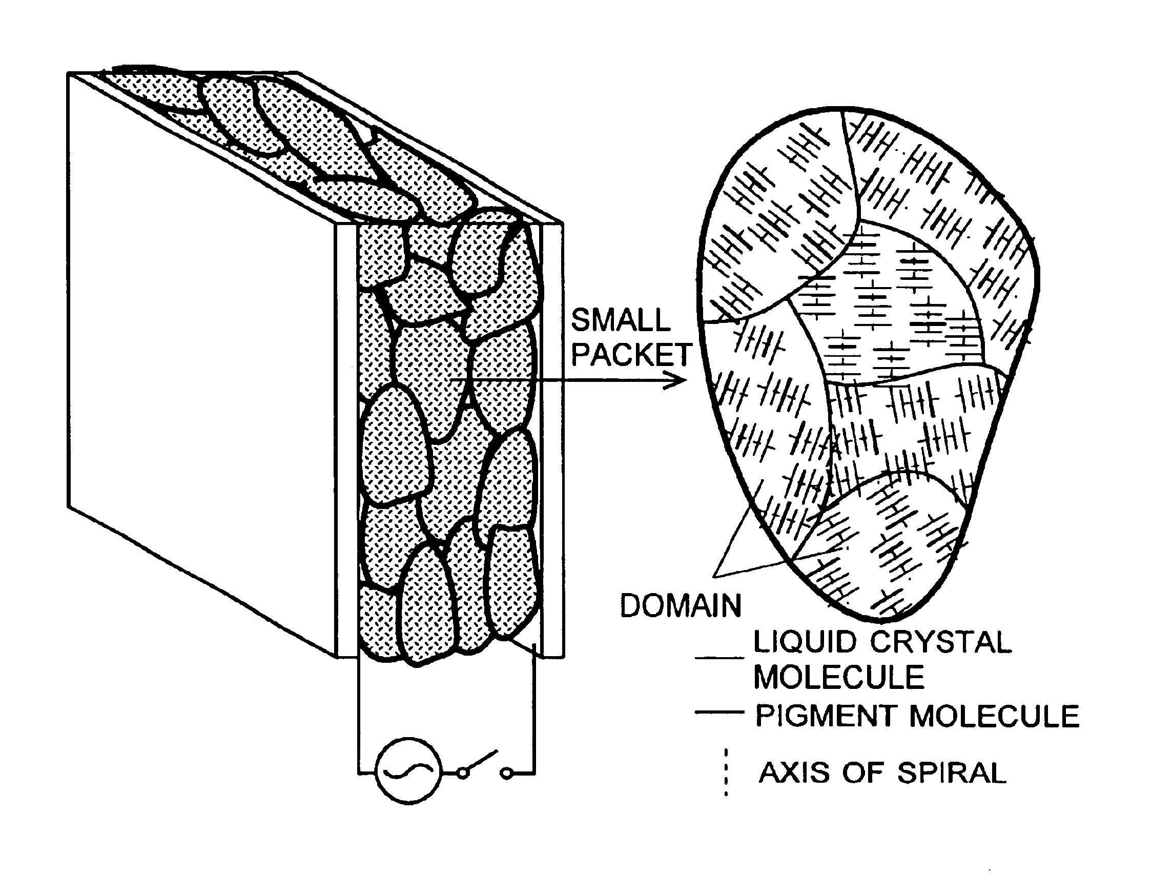
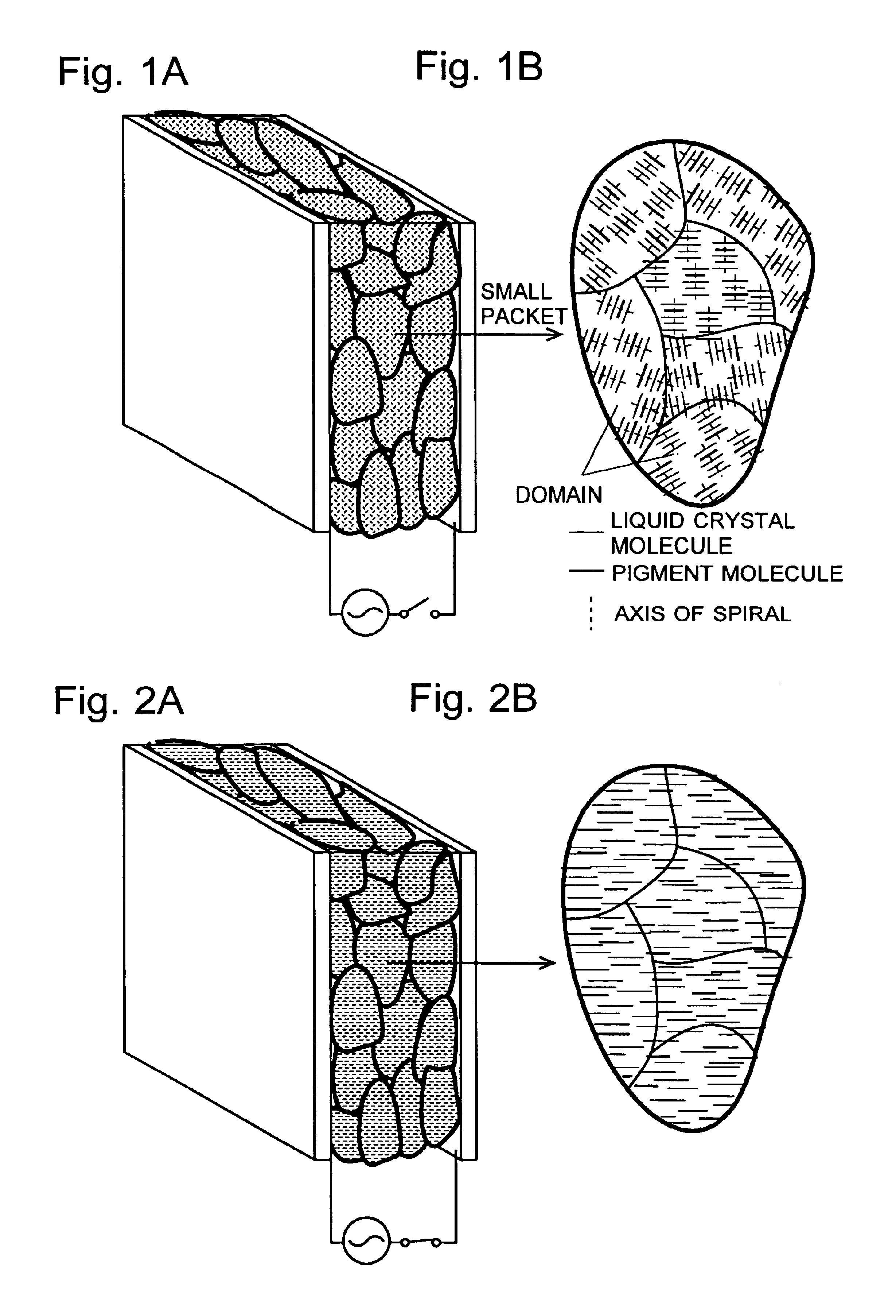
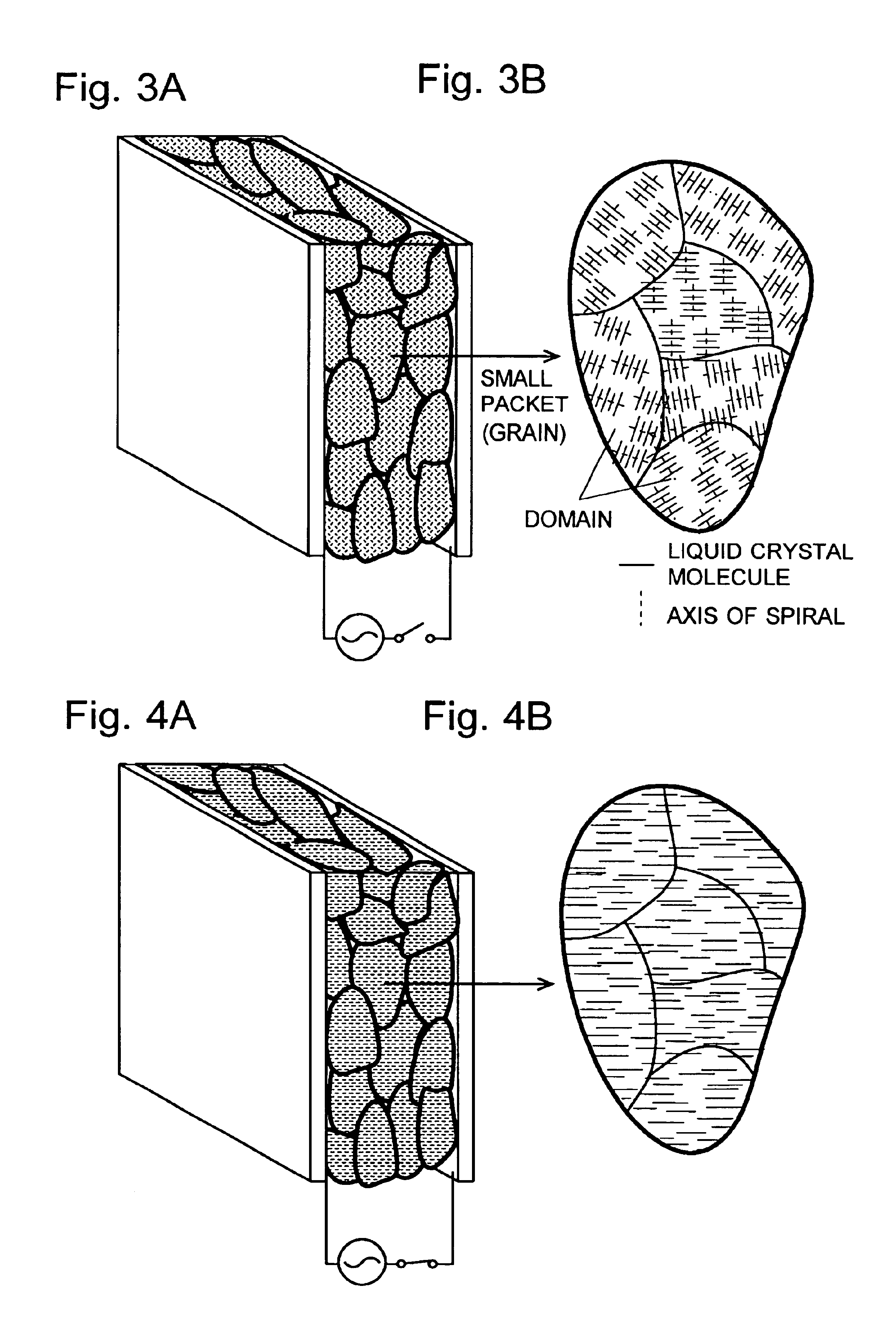
Liquid crystal display device and its production method
a liquid crystal display and display device technology, applied in liquid crystal compositions, instruments, chemistry apparatus and processes, etc., can solve the problems of narrow view angle, difficult to enlarge the screen, less display brightness, etc., and achieve high response speed
- Summary
- Abstract
- Description
- Claims
- Application Information
AI Technical Summary
Benefits of technology
Problems solved by technology
Method used
Image

Examples
Embodiment Construction
[0079]Examples of the present invention are described in detail below. It should be noted that the present invention is not limited to these examples. The electro-optical characteristics of the devices produced in the examples were measured with a function generator “1920A” (produced by NF Corporation) as the power supply and a 150 W (100V) halogen lamp as the light source. Samples were set at a distance of 10 cm from the lamp house including the halogen lamp and the white light filter for a microscope (furthermore, color filters for red, blue and green may be added, if necessary). A light flux having a diameter of 5 mm was irradiated into the sample. The amount of light flux that had passed through the sample and also through a slit with the width of 5 mm in diameter located at a distance of 20 cm was detected with a photo detector. The maximum contrast ratio (T100 / T0) was calculated from the maximum transmissivity (T100) detected while a voltage is applied and the transmissivity (...
PUM
| Property | Measurement | Unit |
|---|---|---|
| distance | aaaaa | aaaaa |
| diameter | aaaaa | aaaaa |
| diameter | aaaaa | aaaaa |
Abstract
Description
Claims
Application Information