Method and system for detecting a spatial movement state of moving objects

a technology for moving objects and states, applied in the field of methods and systems for detecting the spatial movement state of moving objects, can solve the problems of errors in the determination of driving state, restraint systems, navigation systems, previous automotive systems, etc., and achieve the effects of increasing equipment complexity, cost saving, and increasing transparency

Inactive Publication Date: 2005-08-02
ROBERT BOSCH GMBH
View PDF23 Cites 34 Cited by
  • Summary
  • Abstract
  • Description
  • Claims
  • Application Information

AI Technical Summary

Benefits of technology

[0015]It is possible to achieve the following advantages with the method according to the present invention and the system according to the present invention for detecting the spatial movement state of moving objects, e.g., vehicles:—central detection of the spatial movement state. In the past, the movement state has been detected and analyzed separately by each subsystem which has meant a great increase in equipment complexity;—saving on program code in vehicle systems because they are no longer performing the measurement

Problems solved by technology

Previous automotive systems (e.g., ESP: electronic stabilizing program), restraint systems, and navigation systems are limited to the detection of planar movements of the vehicle and involve one-dimensional or two-dimensional measurement tasks.
Interpretation of these measurement results may result in errors in determination of the driving state.
These errors are small in normal driving states but in various driving states such as driving on a steep curve, driving on a steep inclinat

Method used


Image

  • Method and system for detecting a spatial movement state of moving objects
  • Method and system for detecting a spatial movement state of moving objects
  • Method and system for detecting a spatial movement state of moving objects

Examples


Embodiment Construction

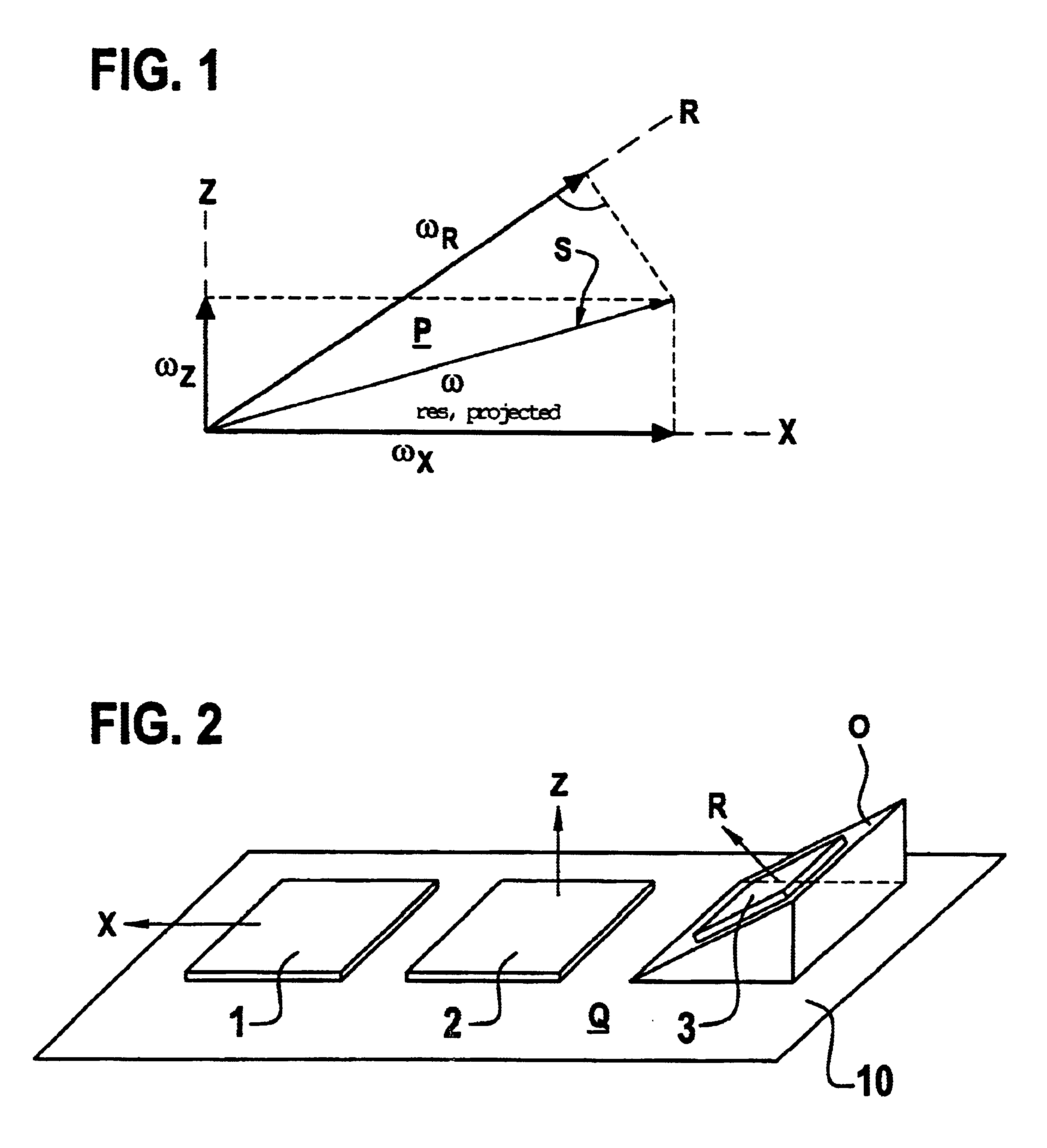
[0026]FIG. 1 shows a vector diagram to illustrate a first example embodiment of the method according to the present invention which permits partial detection of the spatial movement state.

[0027]Partial detection of the spatial movement state provides that redundant information may be generated even with a few sensors, e.g., three sensors here, if one is interested only in the movement component in the plane in which the sensors also do their detecting.

[0028]Vector ωX illustrates a first rotational rate vector (angular velocity) which is the detection of the rate of rotation about the longitudinal axis of the vehicle (X axis) in the case of a motor vehicle, such as that detected for rollover applications. A second vector ωZ perpendicular to first vector ωX illustrates the detection of the rotation of a vehicle about the vertical axis (Z axis) using another rotational rate sensor. The detection directions of these two first rotational rate sensors are perpendicular to one another and ...


PUM


Abstract

A method and a system for detecting the spatial movement state of moving objects, e.g., vehicles. Due to a, for example, non-cartesian arrangement of four rotational rate sensors and/or acceleration sensors, it is also possible to obtain a redundant signal in addition to the desired useful signal indicating the spatial movement state, e.g., the rotational movement and/or acceleration in space; if this redundant signal is large enough in comparison with the rotational rate actually applied, it may be used for detection of the size of the error and the defective sensor. The four sensors are mounted, for example, on a sensor platform forming a three-sided truncated pyramid so that all possible three-way combinations of sensors are mutually linearly independent. The accuracy about the vertical axis is defined by the angle of inclination of the side faces of the truncated pyramid.

Description

FIELD OF THE INVENTION[0001]The present invention relates to a method and a system for detecting a spatial movement state of moving objects, e.g., vehicles.BACKGROUND INFORMATION[0002]Previous automotive systems (e.g., ESP: electronic stabilizing program), restraint systems, and navigation systems are limited to the detection of planar movements of the vehicle and involve one-dimensional or two-dimensional measurement tasks. With advances in automotive engineering, there is a demand for detecting the spatial state of driving or motion. A variety of additional information may be made available through central detection of the spatial movement state. This information includes the inclination of the vehicle, which makes it possible to regulate the lighting, the displacement of the shift point of automatic operation on an inclination, etc., detection of a rollover and thus a more targeted deployment of airbags, recognition of steep curves, which may be used to improve the ESP algorithm,...

Claims


Application Information

Patent Timeline
IPC IPC(8): B60R21/01G01C21/10G01P15/18G01C21/16H05K3/30B60R21/0132G01P9/04
CPCB60R21/0132G01C21/16G01P15/18B60R2021/01184B60R2021/0119B60R2021/01327H05K3/301G01C21/166G01C21/183G01C17/00
Inventor KRIEG, DIETMARNEUL, REINHARDPAPATHANASSIOU, DOROTHEAMUELLER-FIEDLER, ROLANDKNAUSS, MICHAEL
Owner ROBERT BOSCH GMBH
Why Eureka
Try Eureka