Air, electric and hydraulic landing gear jack

a landing gear and electric technology, applied in the direction of lifting vehicle fittings, vehicle maintenance, transportation and packaging, etc., can solve the problems of manual rotation of the hand crank, manual operation of the jack structure, and difficulty in use, so as to achieve convenient use, low cost, and easy use

Inactive Publication Date: 2005-08-09
DANIEL JEFFREY
View PDF38 Cites 40 Cited by
  • Summary
  • Abstract
  • Description
  • Claims
  • Application Information

AI Technical Summary

Benefits of technology

[0018]It is another object of the present invention to provide a landing gear system that can be operated remotely.
[0019]It is another object of the present invention to provide a landing gear actuating system which is inexpensive to manufacture.
[0020]It is yet another object of the present invention to provide a landing gear actuating system which is easy to use.
[0021]It is still another object of the present invention to provide a landing gear actuating system which is safe to use.
[0022]It is yet another object of the present invention to provide a landing gear actuating system which can be selectively left attached to a trailer during transport thereof or else can be readily detached to interchange the type of motor used to actuate the landing gear system.
[0023]Briefly, the preferred embodiment of the present invention is a landing gear mechanism disp

Problems solved by technology

Manual rotation of the handle in one direction causes extension of the feet and lifting of the trailer to, for example, separate the trailer from a semi-tractor, and requires considerable time and effort on the part of the person manually rotating the hand crank.
Manually operated jack structures, however, are often difficult to use, require much time for their operation and expose the operator to potential injuries as he is positioned next to the trailer while turning the crank to raise or lower the landing gear to in turn raise or lower the trailer.
While other types of gear configurations, such as worm gears, have been used in gear boxes, they have not been incorporated into the gearing of landing gear assemblies because of the need to incorporate gear reduction boxes within the assembly.
In other words, worm gears in combination with gear reduction boxes would reduce the effectiveness of the gear reduction boxes by altering the two speeds of the gear box.
Generally, such retrofitted devices require an intricate system of spacers, pulleys and gearing that is both comparatively expensive and difficult to implement.
Typically, even beyond the general retrofit system, such pneumatic devices require a complex system to receive pressurized air for the actuators to rotate the crank shaft of the gear reduction assembly to raise and lower the landing gear.
Of course, those skilled in the art will understand that due to their pulsating drive mechanism, such pneumatic impact motors are not conducive to the desired smooth operation of raising and lowering the landing gear legs, especially in com

Method used


Image

  • Air, electric and hydraulic landing gear jack
  • Air, electric and hydraulic landing gear jack
  • Air, electric and hydraulic landing gear jack

Examples


Embodiment Construction

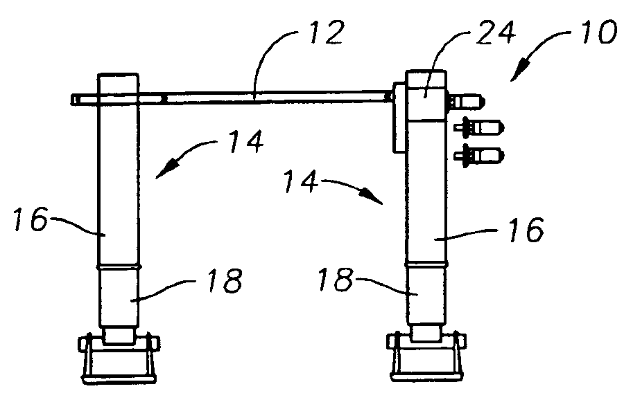
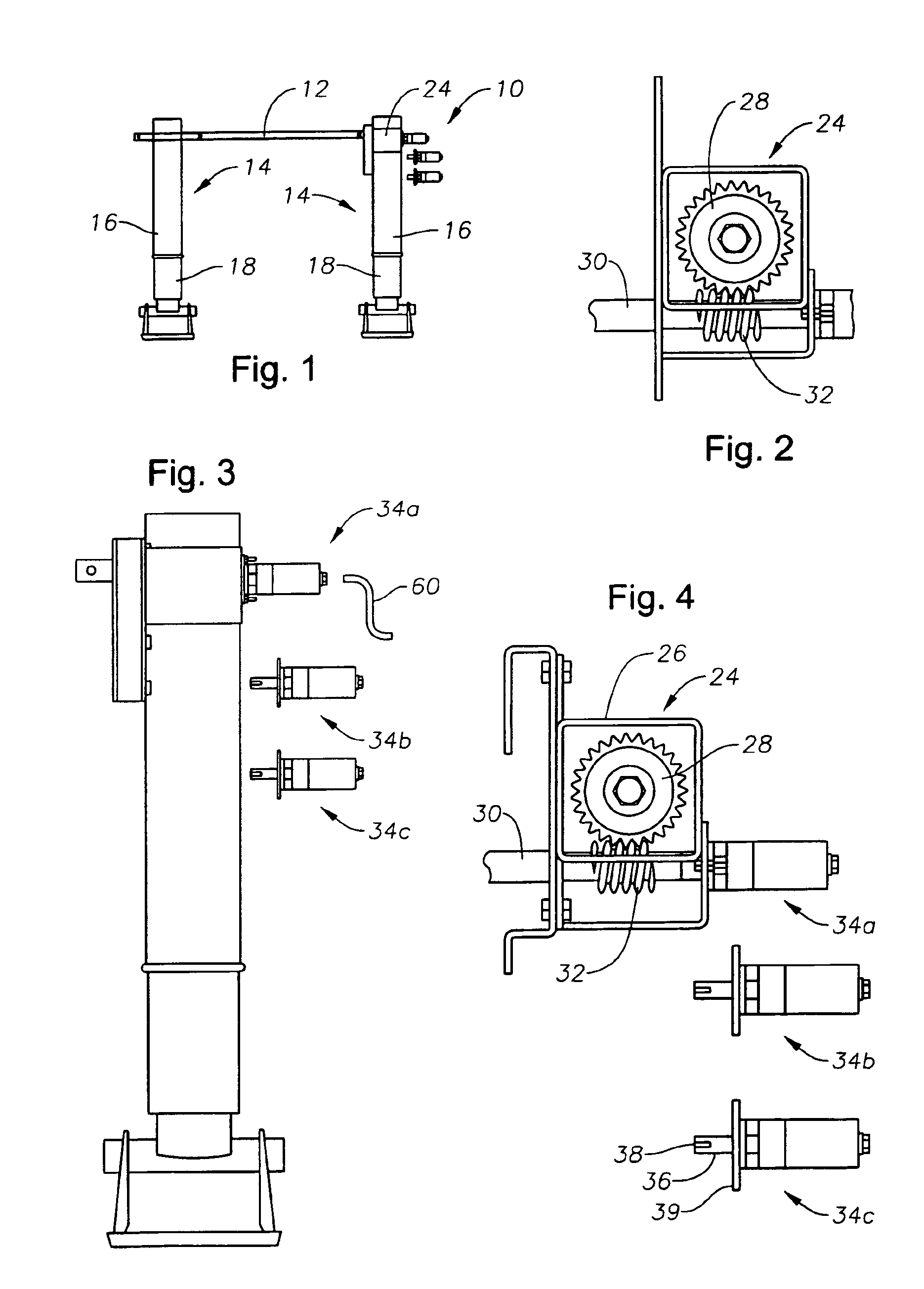
[0030]FIG. 1 depicts a conventional landing gear assembly 10. As can be seen in the view of FIG. 1, the landing gear 10 has a drive shaft 12 which passes through the upper ends of a pair of telescoping legs 14. Each leg 14 has an outer tubular body 16 in which an inner tubular portion 18 is telescopically received. Pivotally mounted feet, wheels or pads 20 attach to the distal end of each inner tubular portion 18. Conventional gear mechanisms (not shown) cause the inner tubular portion 18 to raise or lower, depending upon the direction of rotation of the drive shaft 12. It should be noted that the landing gear need not include a gear reduction box as is common in prior art landing gear configurations.

[0031]Attached to drive shaft 12 is worm gear drive 24. As illustrated in FIG. 2, worm gear drive 24 includes a outer box 26 in which is pivotally mounted a spur gear 28. Also pivotally mounted within box 26 is an input shaft 30 which is provided with a threaded portion 32 that engages ...


PUM


Abstract

A trailer landing gear drive system in which pneumatic, hydraulic and electric motors, as well as the traditional hand crank, are easily interchangeable. The landing gear jack mechanism is disposed to easily connect to any one of these drive motors. The system can utilize any one of the three motor combinations without making any change to the jack itself. Each drive motor output shaft is keyed to connect to the input shaft driving the worm gear of the jack. The output shaft of each type of motor is keyed the same so that the motors are swappable with respect to the input shaft of the landing gear. The hand crank shaft is also keyed to be the same as the keyed motor output shafts. Each motor may include a flange to permit it to be secured to the landing gear. The system eliminates the gear reduction box and replaced it with a worm gear. Furthermore, the system can be operated remotely so that the operator need not be exposed to the perils of weather, a shifting load, other vehicles in the vicinity or other similar hazards.

Description

BACKGROUND OF THE INVENTION[0001]1. Field of the Invention[0002]The present invention relates to semi-trailer landing gear extension and retraction mechanisms, and more particularly to a landing gear mechanism that can be actuated by inexpensive, easily interchangeable pneumatic, hydraulic and electric motors as well as the traditional hand crank.[0003]2. Description of the Prior Art[0004]Many semi-trailers have front landing gear for support of the front of the trailer when the tractor is detached. Such landing gears generally have two spaced-apart, telescoping or Jack-type landing gear legs and feet which extend downwardly from the floor of the trailer. Each leg is operatively attached to screw and follower or a rack and pinion gear arrangement which is driven by a landing gear drive shaft which extends between the legs and which causes extension or retraction of the legs and feet depending on the direction in which it is rotated.[0005]Traditionally, a hand operable handle or cran...

Claims


Application Information

Patent Timeline
IPC IPC(8): B60S9/08B60S9/00
CPCB60S9/08
Inventor DANIEL, JEFFREY
Owner DANIEL JEFFREY
Why Eureka
Try Eureka