System and method for draining remaining water in fuel cell

a fuel cell and system technology, applied in the direction of transportation hydrogen technology, chemistry apparatus and processes, electrochemical generators, etc., can solve the problems of difficult fuel cell restart, complicated system structure, and damage to solid polymer electrolyte membranes, so as to achieve the effect of easy draining and sudden increase of the flow velocity of reaction gas in each gas passag

Inactive Publication Date: 2005-08-09
HONDA MOTOR CO LTD
View PDF4 Cites 5 Cited by
  • Summary
  • Abstract
  • Description
  • Claims
  • Application Information

AI Technical Summary

Benefits of technology

[0025]According to the above method, after the pressure of the gas in the gas passage is increased, the increased gas is released when, for example, the gas pressure exceeds a predetermined pressure. Therefore, the flow velocity of the reaction gas in each gas passage can be suddenly increased. According to the conditions of the present invention for forcibly and easily draining the remaining water, the remaining water can be reliably drained outside the fuel cell.

Problems solved by technology

Therefore, it is difficult to restart the fuel cell.
However, if a dedicated gas supply line is provided as in the above conventional fuel cell power generating system, the system structure is complicated.
In addition, passing of the dried purification gas produces an excessively dried state inside the fuel cell, so that the solid polymer electrolyte membrane may be damaged.

Method used


Image

  • System and method for draining remaining water in fuel cell
  • System and method for draining remaining water in fuel cell
  • System and method for draining remaining water in fuel cell

Examples


Embodiment Construction

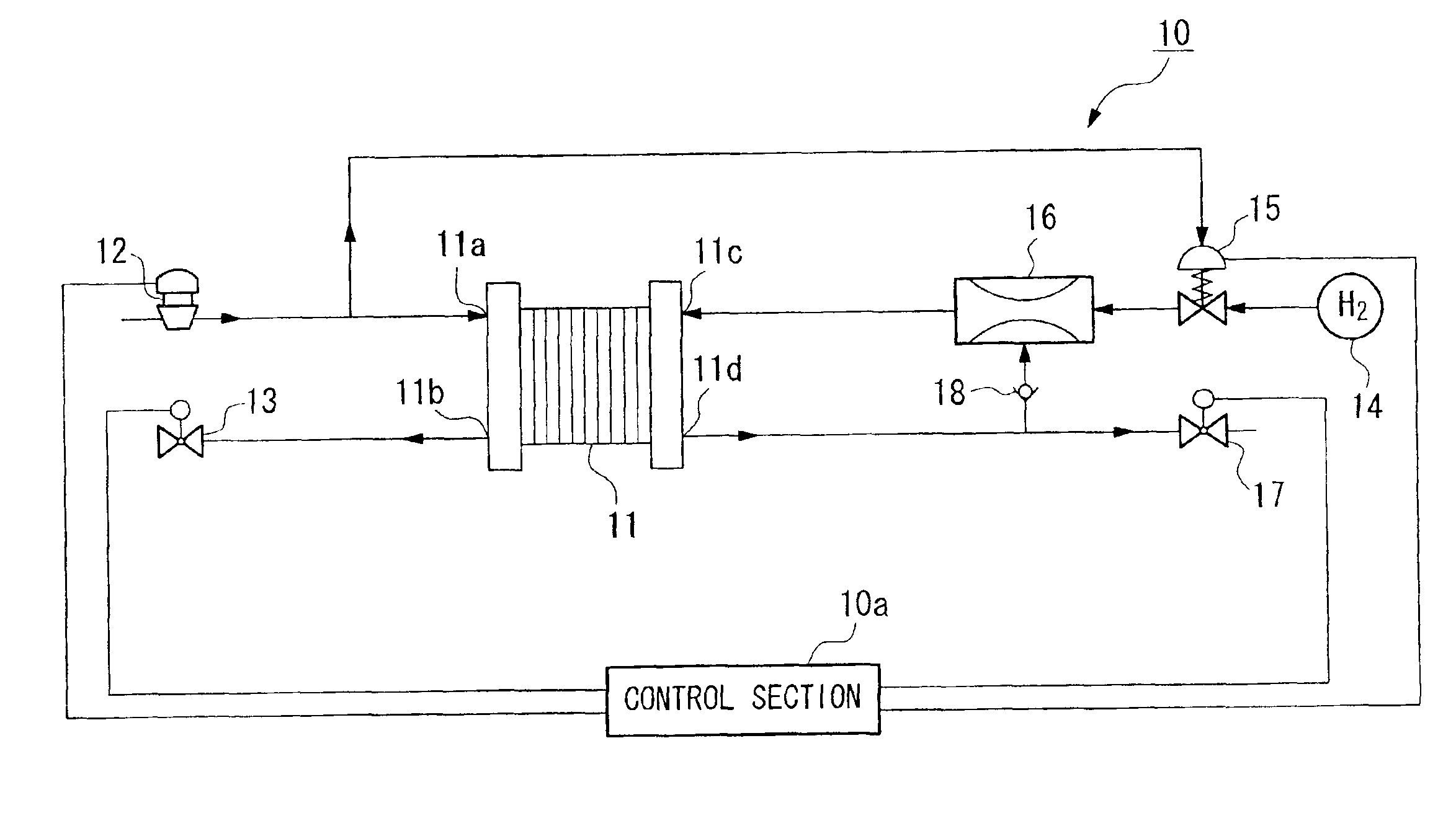
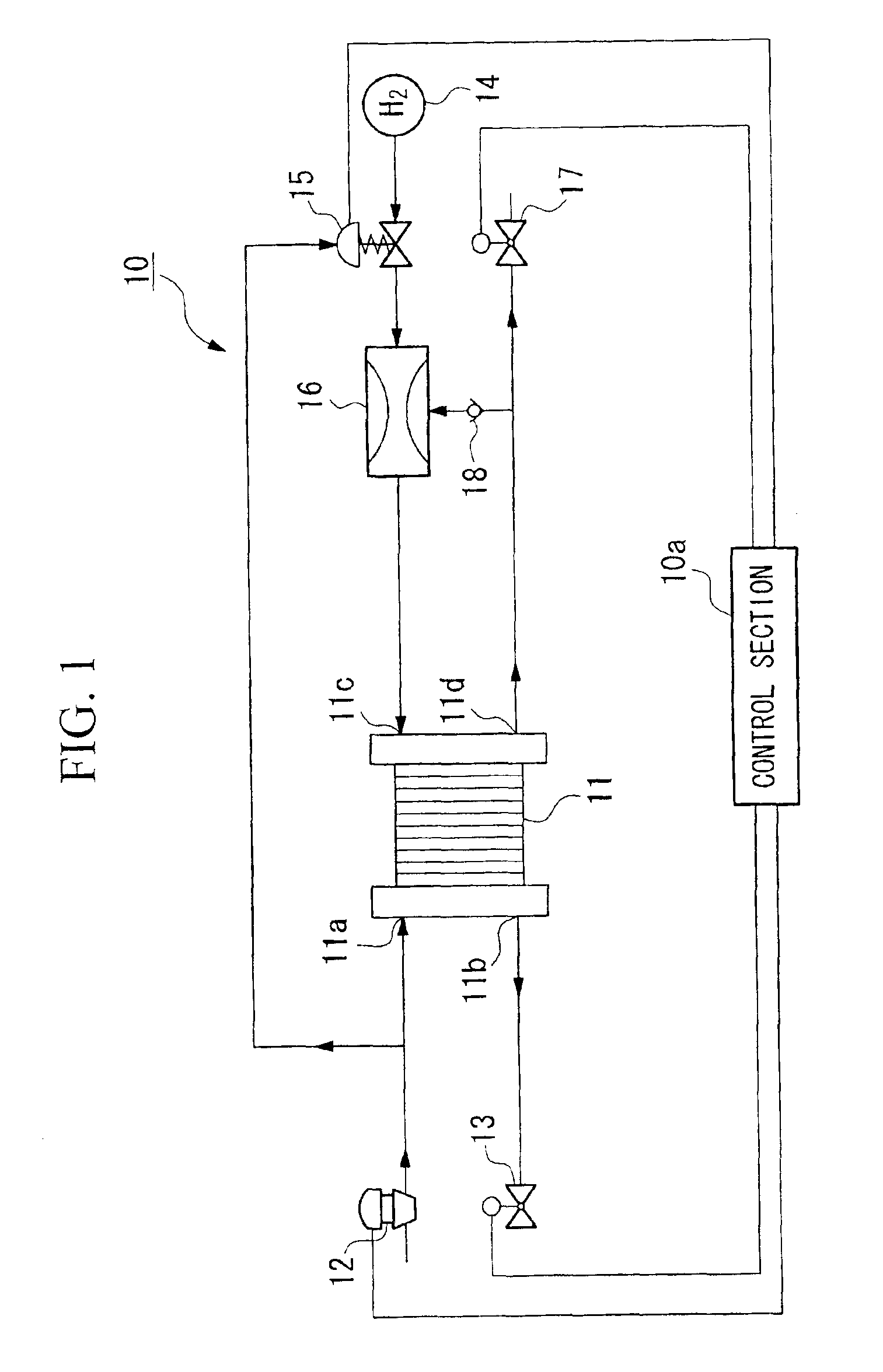
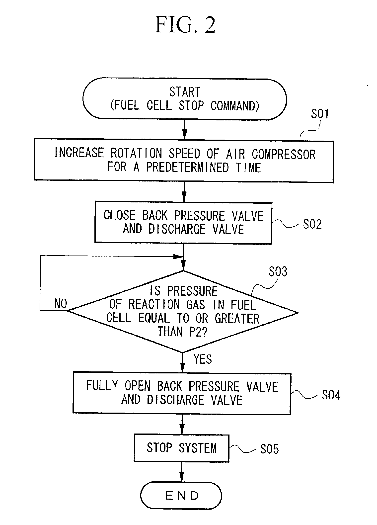
[0032]Hereinafter, the structure of the system for draining remaining water in a fuel cell as an embodiment of the present invention will be explained with reference to the drawings. FIG. 1 is a diagram showing the structure of the system (10).

[0033]That is, the remaining water draining system 10 according to the present embodiment is built, for example, in a vehicle such as an electric car. The system comprises a control section 10a, a fuel cell 11, an air supply section 12, a back pressure valve 13, a fuel supply section 14, a fuel supply side pressure control section 15, an ejector 16, and a discharge valve 17. The control section 10a controls the operation of each section which connected to the control section 10a.

[0034]In the fuel cell 11, each unit cell has an anode and a cathode which are provided on either side of a solid polymer electrolyte membrane which may be a solid polymer ionic exchange membrane. A plurality of the unit cells are stacked so as to form a stack. The fu...


PUM

PropertyMeasurementUnit
pressureaaaaaaaaaa
pressureaaaaaaaaaa
flow rateaaaaaaaaaa

Abstract

A system and method for draining remaining water in a gas passage of a fuel cell, which has a simple structure and the remaining can be efficiently and reliably drained outside. Water which remains in a gas passage of the fuel cell is first drained by increasing the flow rate of the reaction gas while the operation of the fuel cell is stopped. The remaining water which has not been drained is then drained by increasing the pressure of the reaction gas and then decreasing the increased pressure. The increase and decrease operation of the pressure of the reaction gas is started after the increase of the flow rate of the reaction gas is started. Typically, the increase of the pressure of the reaction gas is started when a predetermined time has elapsed after the increase of the flow rate of the reaction gas is started.

Description

BACKGROUND OF THE INVENTION[0001]1. Field of the Invention[0002]The present invention relates to a system and method for draining remaining water in a fuel cell, and in particular, relates to an art for draining remaining water outside, which remains in reaction-gas passages of a fuel cell.[0003]2. Description of the Related Art[0004]In conventional solid polymer electrolyte membrane fuel cells, each cell has an anode and a cathode which are provided on either side of a solid polymer electrolyte membrane. Plural such cells are stacked so as to form a stack, which is called a “fuel cell” in the following explanations. In the fuel cell, hydrogen, which functions as fuel, is supplied to the anode, while air, which functions as an oxidizing gas, is supplied to the cathode. The catalytic reaction on the anode generates hydrogen ions, and the hydrogen ions are transferred to the cathode via an electrolyte membrane. The transferred hydrogen ions react with oxygen on the cathode, thereby ge...

Claims


Application Information

Patent Timeline
Patent Type & Authority Patents(United States)
IPC IPC(8): B01J4/00H01M8/10H01M8/04H01M8/00H01M8/06
CPCH01M8/04179H01M8/04223H01M8/04388H01M8/04395H01M8/04753H01M8/04828H01M2250/20Y02E60/50Y02T90/32Y02T90/40H01M8/241H01M8/04303H01M8/04228H01M8/2457
Inventor KATO, HIDEOHAYASHI, KATSUMIUOSHIMA, MINORU
Owner HONDA MOTOR CO LTD
Why Eureka
Try Eureka