Asymmetric memory cell

a memory cell and asymmetric technology, applied in the field of integrated circuit memory cell arrays, can solve the problems of change in cmr resistance, device more susceptible to process tolerance errors, and application not suitable for dense memory array applications

Active Publication Date: 2005-08-09
SAMSUNG ELECTRONICS CO LTD
View PDF4 Cites 5 Cited by
  • Summary
  • Abstract
  • Description
  • Claims
  • Application Information

AI Technical Summary

Problems solved by technology

These devices work in limited applications, but they are not suitable for dense memory array applications because of relatively large size of these cells.
However, when a high electric field induces current flow through the CMR material, a change in the CMR resistance can result.
However, smaller feature sizes make the device more susceptible to process tolerance errors.
Due to process tolerances, extremely small geometrically asymmetric devices are not always practical.
However, an analysis (provided below) shows that fabricated memory cells that are sufficiently geometrically symmetric will not work properly.
Even if these symmetrical devices can be programmed, the net resistance change from high resistance-state to low resistance-state may be relatively low.

Method used


Image

  • Asymmetric memory cell
  • Asymmetric memory cell
  • Asymmetric memory cell

Examples


Embodiment Construction

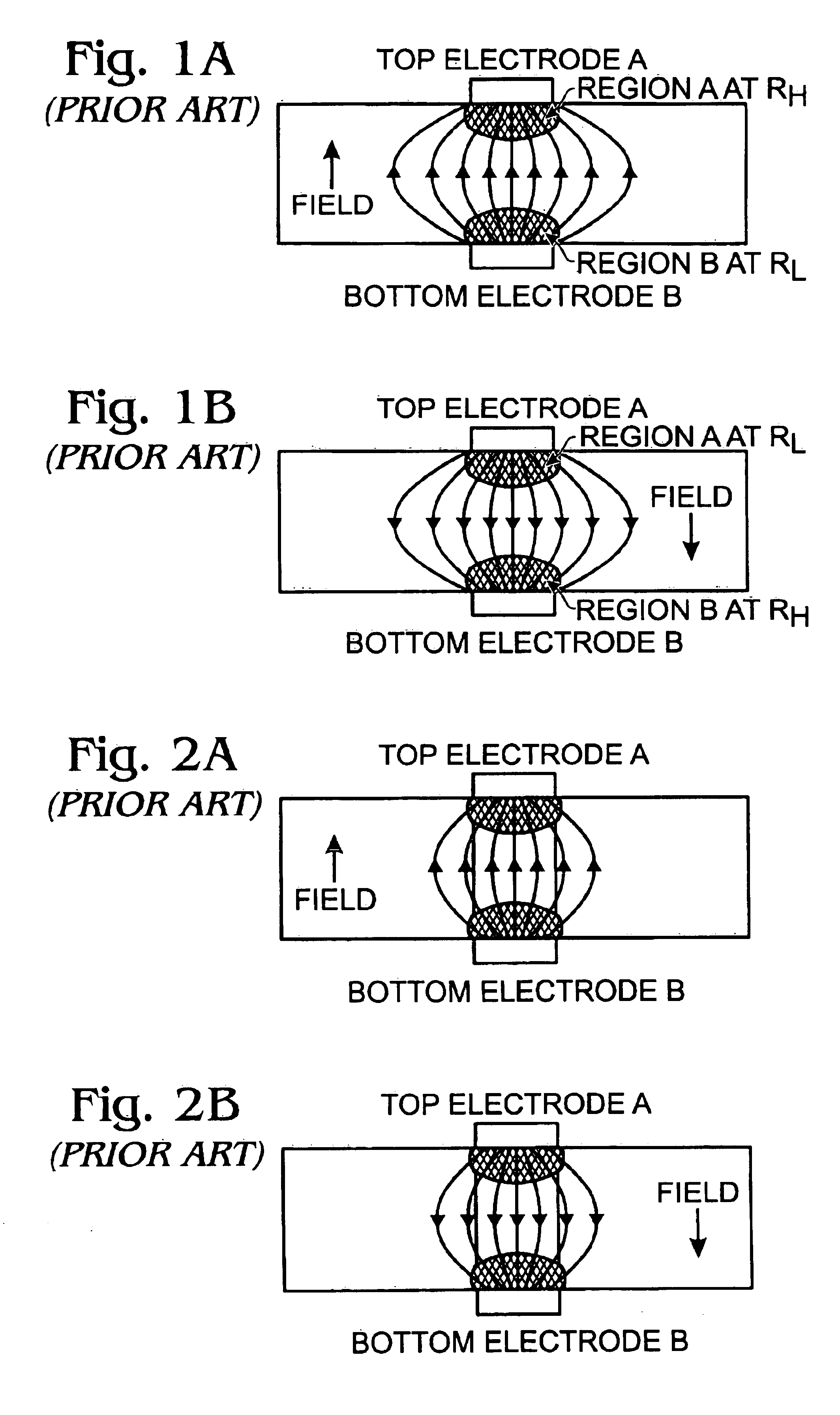
[0018]FIGS. 1A and 1B are partial cross-sectional views of a memory cell during programming (FIG. 1A) and erasing (FIG. 1B) operations. The top and bottom electrodes are identical and the memory resistance material is uniform throughout. If the geometric structure of the device could be made perfectly symmetrical, the net resistance would remains constant, in a high-resistance state, when either a negative field (FIG. 1A) or a positive field (FIG. 1B) is applied. Note that a field direction is defined with respect to the top electrode. That is, the field is considered to be induced from the top electrode. In such circumstances, programming is not possible. Therefore, a geometrically symmetric device structure, such as one in FIGS. 1A and 1B, is not practical.

[0019]More specifically, the geometrically symmetric memory cell has a high current density near the electrodes (regions A and B), and a low current density in the center portion of the device, in the presence of an electric fie...


PUM


Abstract

An asymmetric memory cell and method for forming an asymmetric memory cell are provided. The method comprises: forming a bottom electrode having a first area; forming an electrical pulse various resistance (EPVR) material overlying the bottom electrode; forming a top electrode overlying the EPVR layer having a second area, less than the first area. In some aspects the second area is at least 20% smaller than the first area. The EPVR is a material such as colossal magnetoresistance (CMR), high temperature super conducting (HTSC), or perovskite metal oxide materials. The method further comprises: inducing an electric field between the electrodes; inducing current flow through the EPVR adjacent the top electrode; and, in response to inducing current flow through the EPVR adjacent the top electrode, modifying the resistance of the EPVR. Typically, the resistance is modified within the range of 100 ohms to 10 mega-ohms.

Description

BACKGROUND OF THE INVENTION[0001]1. Field of the Invention[0002]This invention generally relates to integrated circuit (IC) memory cell arrays and, more particularly, to an asymmetrical memory resistance memory cell and method for fabricating the same.[0003]2. Description of the Related Art[0004]Conventionally, memory cells using a memory resistor material, such as colossal magnetoresistance (CMR) materials, are fabricated with large unpatterned conductive bottom electrodes, unpatterned CMR material, and relatively small top electrodes. These devices work in limited applications, but they are not suitable for dense memory array applications because of relatively large size of these cells.[0005]The CMR material can be said to have a non-volatile nature, as the resistance of the CMR material remains constant under most circumstances. However, when a high electric field induces current flow through the CMR material, a change in the CMR resistance can result. During a programming proces...

Claims


Application Information

Patent Timeline
Patent Type & Authority Patents(United States)
IPC IPC(8): G11C11/15G11C11/02H01L27/10G11C13/00H01L21/8246H01L27/105H01L43/08
CPCB82Y10/00G11C11/15G11C13/0007H01L45/04H01L45/1233H01L45/147H01L45/1253G11C2213/31G11C2213/52H10N70/20H10N70/841H10N70/8836H10N70/826A47G21/103A47G2400/02
Inventor HSU, SHENG TENGLI, TINGKAIEVANS, DAVID R.
Owner SAMSUNG ELECTRONICS CO LTD
Why Eureka
Try Eureka