Transmission and reception interface and method of data transmission

a technology of reception interface and data transmission, applied in the field of transmission and reception interface, can solve the problems of reducing the transmission speed, reducing the transmission efficiency, and reducing the transmission efficiency, and achieve the effect of faster data transmission and/or faster transmission speed

Inactive Publication Date: 2005-08-09
POLARIS INNOVATIONS LTD
View PDF14 Cites 67 Cited by
  • Summary
  • Abstract
  • Description
  • Claims
  • Application Information

AI Technical Summary

Benefits of technology

[0010]It is the object of the present invention to provide a reception interface and a transmission interface and a method so that data transmission and data synchronization enable a safer and / or faster data transmission.
[0015]The present invention is based on the recognition that the prior separation between the clock signal or synchronization line / s, respectively, and the data lines in transmission between a transmission and a reception interface can be dispensed with, and that a safer and thus eventually even faster data transmission can be obtained by integrating the synchronization information for the transmission of an N-bit signal into an M-bit code into which the N-bit signal is coded.

Problems solved by technology

A disadvantage in the interfaces of the DDR and the SDRAM type is that, by the separation of the data lines from the clock signal lines the lines participating in the data transmission comprise different electrical characteristics and in particular different kinds of loads, which may lead to an impediment of synchronism and thus to a restriction of the transmission speed.
It is of especial disadvantage for the interface of the DDR type illustrated in FIG. 5 that, at the transmission side end of the interface, a circuit, such as for example a DDL (DDL=Delay Locked Loop) (not shown) must be present, which must produce a delay of exactly one fourth of the clock period, and that a stable reference direct voltage VREF must be provided.
Due to the fact that in SDRAM technology no edge-controlled sampling is performed, the data transmission rate in this interface technology is lower and restricted to about 150 MHz for longer busses.
A further disadvantage of these interfaces is that all the lines can switch from 0 to 1 or from 1 to 0 and thus the supply system must be designed for higher peak currents.
As in the interfaces of the DDR SDRAM type and the SDRAM type, however, a disadvantage of the interfaces according to the U.S. patents mentioned above is that the lines taking part in the transmission comprise considerably different electrical kinds of loads, i.e. the data lines are connected to fewer comparators than the source-synchronous voltage and timing reference signals.

Method used


Image

  • Transmission and reception interface and method of data transmission
  • Transmission and reception interface and method of data transmission
  • Transmission and reception interface and method of data transmission

Examples


Embodiment Construction

[0027]An embodiment of the present invention will be described in detail referring to FIGS. 1 to 4.

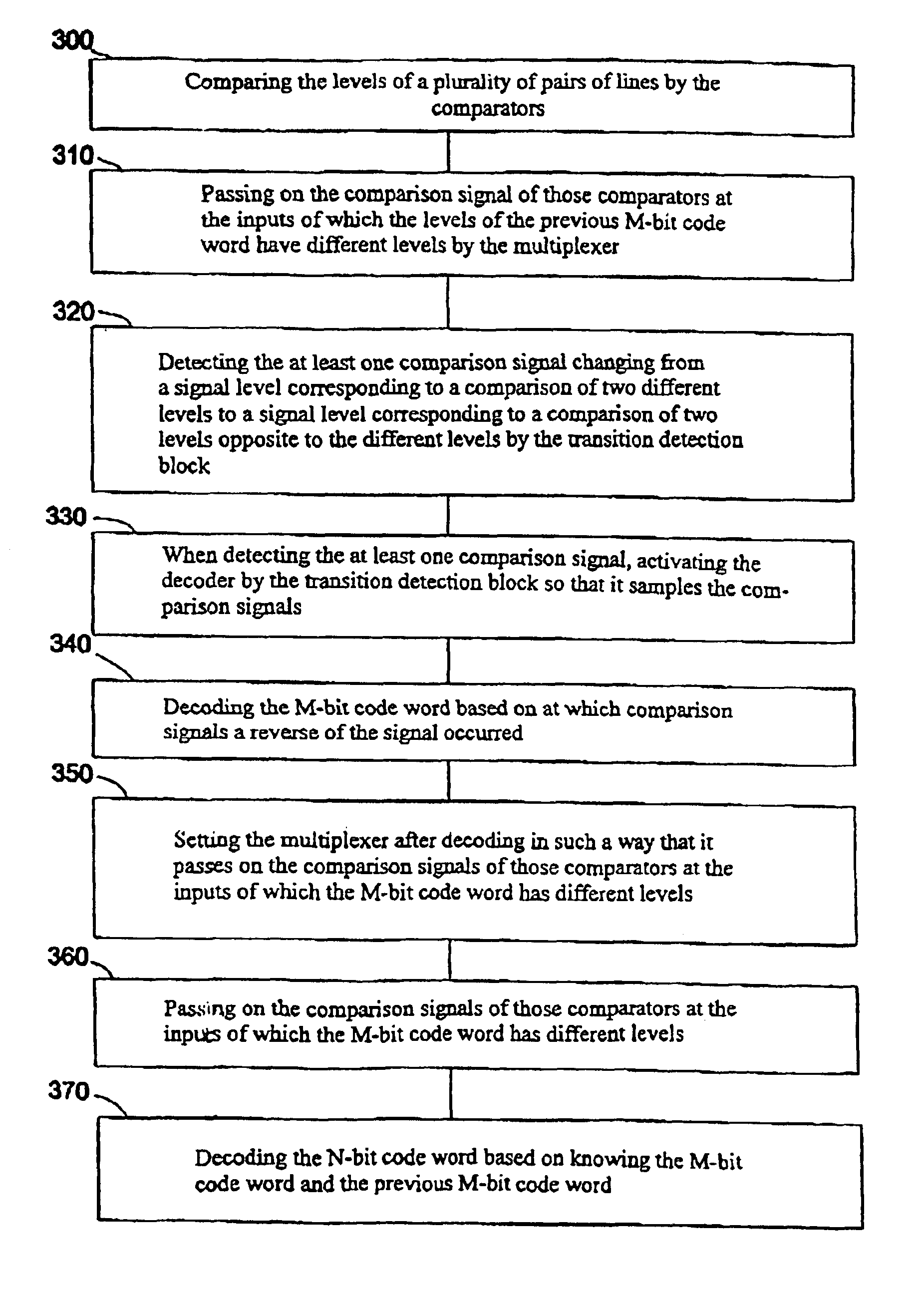
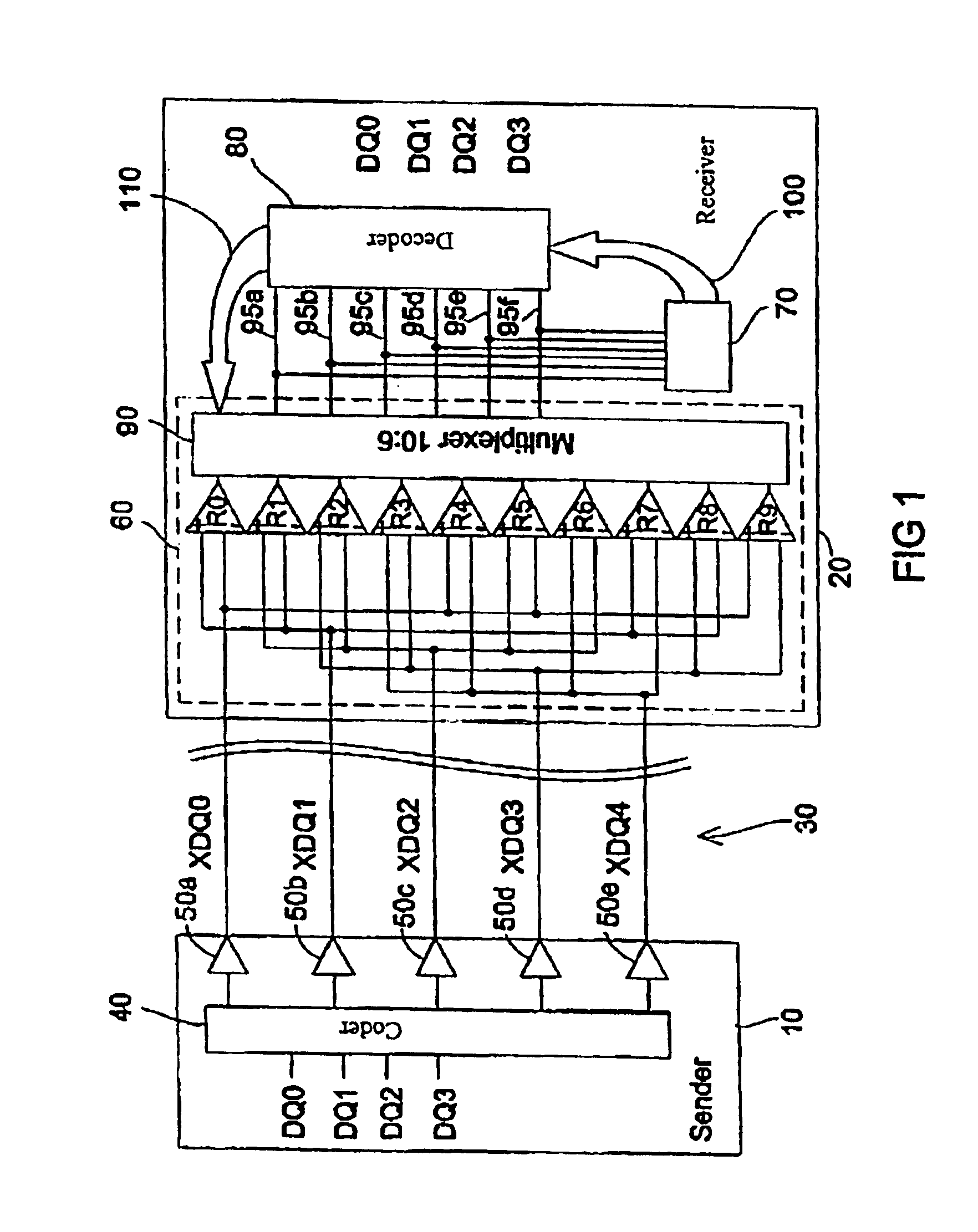
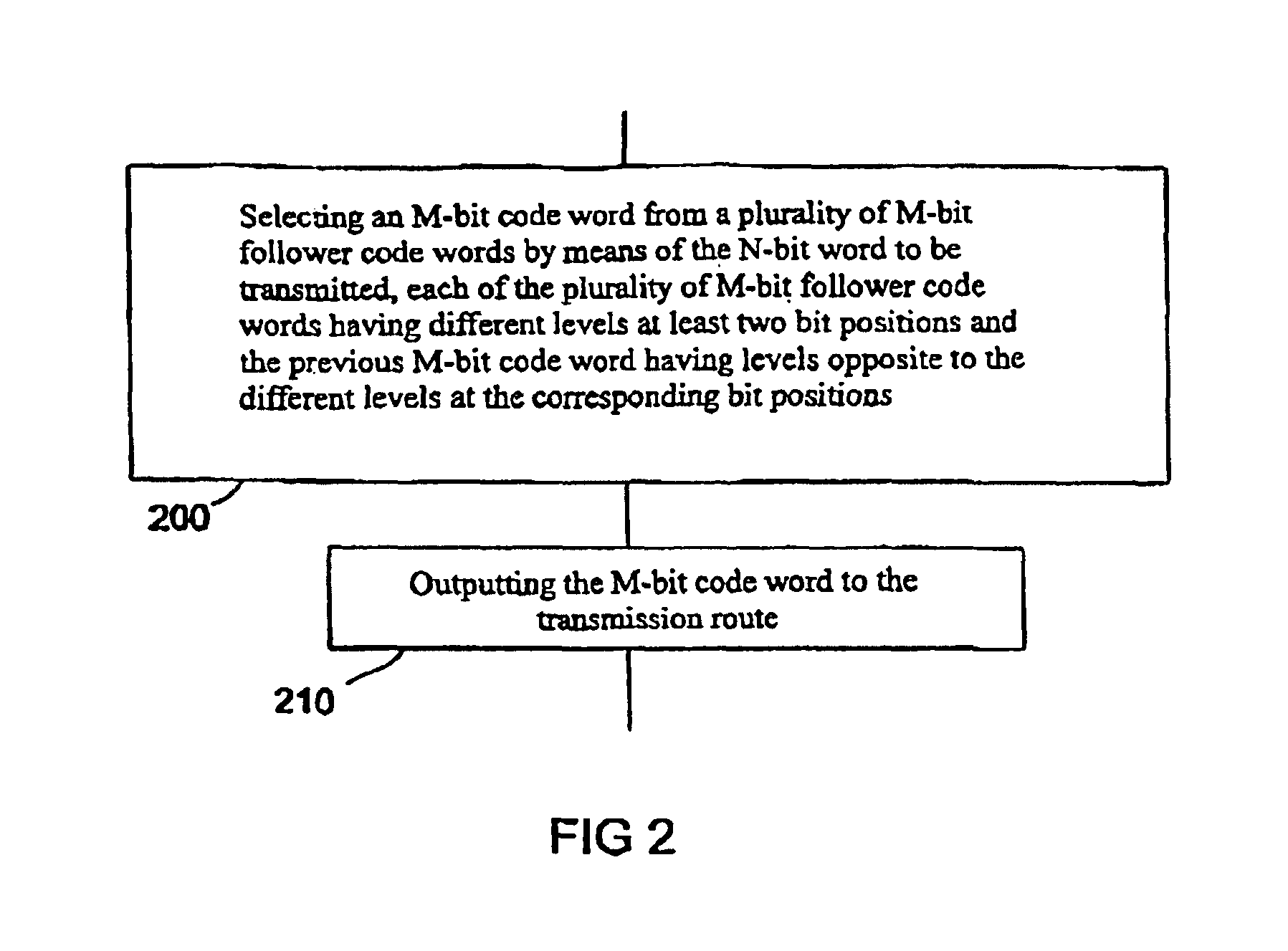
[0028]FIG. 1 shows the block diagram of an interface arrangement of a transmission interface and a reception interface according to an embodiment of the present invention, while FIGS. 2 and 3 illustrate the steps occurring in the transmission interface and the reception interface. FIG. 4 is a table listing, for a part of the code words permitted for coding, information serving for illustrating the mode of operation of the transmission and reception interface of FIG. 1.

[0029]In the following, the architecture of the interface arrangement of FIG. 1 will be explained first. The transmission interface or the sender, respectively, in general shown at 10, is connected to the reception interface or the receiver, respectively, indicated in general at 20, via a 5-bit line 30 consisting of five lines XDQ0, XDQ1, XDQ2, XDQ3 and XDQ4. The sender 10 includes a coder 40 receiving four bits DQ0, DQ1,...


PUM


Abstract

An N-bit word is produced from an M-bit code received on an M-bit line, M being larger than N, the M-bit code comprising at least an M-bit code word and a previous M-bit code word, the M-bit code word comprising different levels at at least two bit positions, and the previous M-bit code word comprising levels opposite to the different levels at the corresponding bit positions, by comparing the levels at the two bit positions of the M-bit code word to obtain a first value, comparing the levels at the two corresponding bit positions of the previous M-bit code word to obtain a second value, detecting that the first value is opposite to the second value, and decoding the M-bit code word responsive to detecting that the first value is opposite to the second value. An advantage of the present invention is that all the lines taking part in the transmission have the same electrical characteristics, the same meaning and the same kind of loads.

Description

BACKGROUND OF THE INVENTION[0001]1. Field of the Invention[0002]The present invention relates to transmission and reception interfaces and especially to the data transmission and data synchronization between sender and receiver, such as, for example, between integrated circuits.[0003]2. Description of Prior Art[0004]The need for fast transmission with simultaneous data synchronization is high, especially in the field of working memories and in particular in the interface between the working memory and the requesting controller. Examples of memory technologies in which synchronization takes place in data transmission are, for example, SDRAM technology (SDRAM=Synchronous Dynamic Random Access Memory) and DDR SDRAM technology (DDR SDRAM=Double Data Rate Synchronous Dynamic Random Access Memory). It is common to all those technologies that in addition to the actual data, such as, for example, read or write data, a clock signal and / or strobe signal is transmitted to obtain synchronizatio...

Claims


Application Information

Patent Timeline
Patent Type & Authority Patents(United States)
IPC IPC(8): H04L25/49H04L7/02H04L7/00
CPCH04L25/4904H04L25/4908H04L7/0066
Inventor KIEHL, OLIVER
Owner POLARIS INNOVATIONS LTD
Why Eureka
Try Eureka