Image processing method and apparatus for converting colors in a color image

a color image and processing method technology, applied in the field of apparatus and a processing method of color images, can solve the problems of circuit scale and increase the manufacturing cost of the processing apparatus, and the image quality is deteriorated, and no conventional color image processing system has both of these kinds of adjustment processing

Inactive Publication Date: 2005-08-09
CANON KK
View PDF25 Cites 17 Cited by
  • Summary
  • Abstract
  • Description
  • Claims
  • Application Information

AI Technical Summary

Benefits of technology

[0024]In view of the above-described problems, an object of the present invention is to provide a color im...

Problems solved by technology

Therefore, in a portion close to the boundary of the converted color, the colors before and after conversion may remain as mottles or speckles because of chattering due to reading non-uniformity or the like, resulting in a considerable deterioration in image quality.
Therefore, the circuit scale and the manufacturing cost of the processing apparatus are increased if the number of functions is increased.
However, no conventional color image processing system has both of these two kinds of adjustment processing.
This is because of the specific formation of the halftone dot image in which constellations of dots having a plurality of colors are superposed in a s...

Method used


Image

  • Image processing method and apparatus for converting colors in a color image
  • Image processing method and apparatus for converting colors in a color image
  • Image processing method and apparatus for converting colors in a color image

Examples


first embodiment

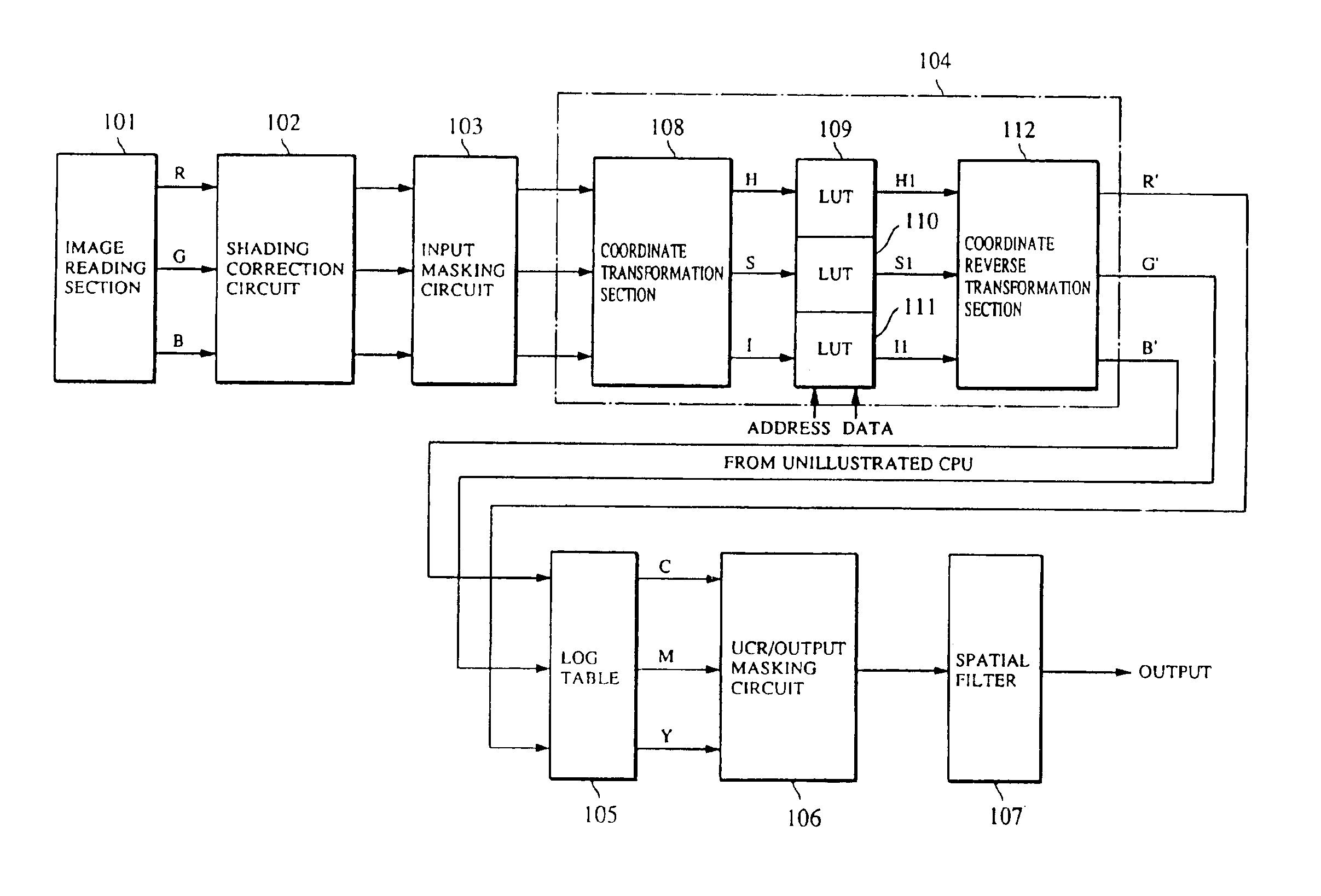
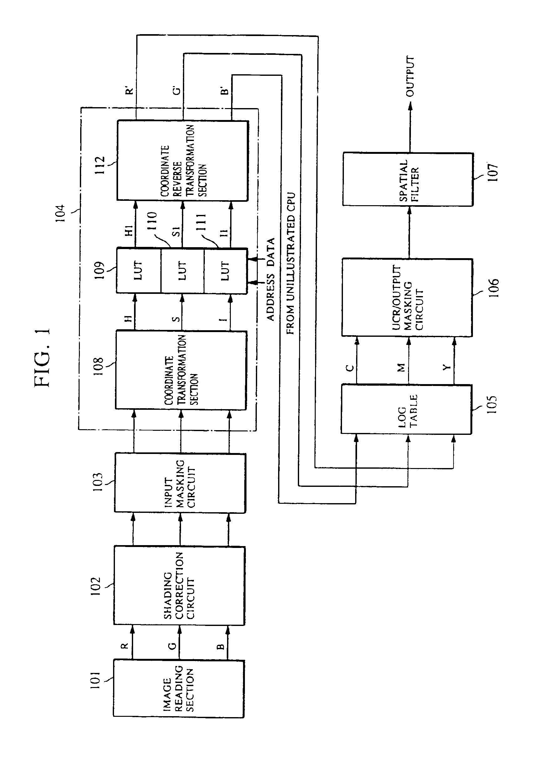
[0058]FIG. 1 shows an example of a circuit of a digital color copying machine in accordance with the first embodiment of the present invention, and FIG. 2 shows the external appearance of a display and an operating panel of the copying machine.

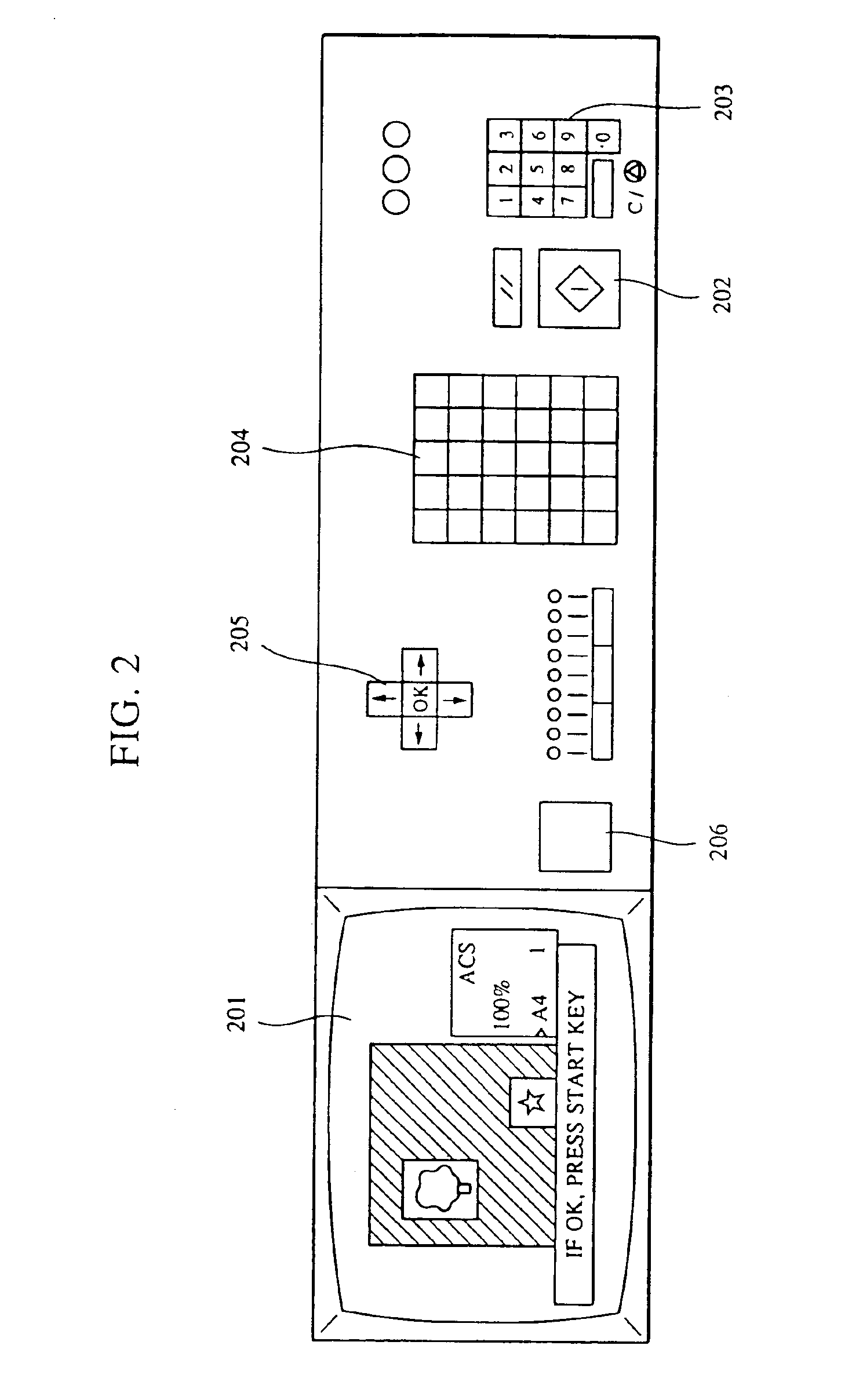
[0059]Referring to FIG. 2, the copying machine has an image display 201, a copying start key 202, a ten key cluster 203, function keys 204, and control keys 205.

[0060]When color conversion processing is started by operating the color conversion mode function keys 204 after setting an original, the original is scanned and an original image is displayed on the image display 201. A color before conversion and a color after conversion, which are selected from colors in the image or from color samples (not shown), are then designated by using a pointing device (not shown) such as a so-called mouse. An image converted in accordance with the designation is displayed. When the start key 202 is pressed, the displayed image is printed out.

[0061]If it is...

second embodiment

[0068]FIG. 4 is a block diagram showing the configuration of color conversion unit 104 in accordance with the second embodiment of the present invention.

[0069]In the first embodiment, the hue H, the saturation S and the intensity I are independently converted by the LUTs 109 to 111, respectively. Alternatively, LUTs can be arranged in such a manner that two or three of the three coordinates are correlated. In such a case, in order to reduce the number of address bits of the LUTs, the number of bits of a main signal in the three signals input to the LUTs, e.g., signal H in the H conversion LUT, is maintained while the numbers of bits of other signals, e.g., signals S and I in the H conversion LUT, are reduced.

[0070]In this embodiment, 8 bits for a main signal and 3 bits for other signals, i.e., 14 bits in total, are input to each of HLUT 401, SLUT 402 and ILUT 403, and an 8-bit signal after conversion is output from each LUT.

[0071]If the three signals are converted by being correlate...

third embodiment

[0072]In the first embodiment, if different kinds of processing are respectively performed on different areas of a color image, area signals are input for addressing in the LUTs, thereby facilitating processing.

[0073]If the coordinate transformation section 108 and the coordinate reverse transformation section 112 are arranged as hardware, there is a possibility of occurrence of an error or bit failure during calculation, which results in a deterioration in image quality. Therefore, the signals R, G and B may pass through the reverse coordinate transformation section 108 and the coordinate transformation section 112 without being processed if the input and the output of each LUT are equal to each other, thereby reducing deteriorations in image quality due to coordinate transformation.

[0074]FIG. 5 shows the configuration of color conversion unit 104 in accordance with the third embodiment of the present invention. A signal MODE 501 designating a conversion mode is supplied. Each of c...


PUM


Abstract

A color image signal is generated and an arbitrary color in the color image signal is set as a color to be converted. A color after conversion is designated. The color to be converted or a color similar to the color to be converted is converted into the color after conversion or a color similar to the color after conversion. By this processing, a color-converted image, in which a conversion boundary is unnoticeable, can be produced.

Description

[0001]This application is a divisional of application Ser. No. 08 / 353,906, filed Dec. 12, 1994, now U.S. Pat. No. 6,434,266.BACKGROUND OF THE INVENTION[0002]1. Field of the Invention[0003]The present invention relates to an apparatus and a method for processing color images and, more particularly, to a color image processing apparatus having a function of replacing a particular color in an original with a different color and a color image processing method using such a function.[0004]2. Description of the Related Art[0005]FIG. 6 shows a conventional color image processing apparatus.[0006]Three color image signals R (red), G (green) and B (blue) representing an image are converted into an intensity signal I, a hue signal H and a saturation signal S by a matrix calculation in a coordinate transformation section 61. Comparators 62a to 62f compare the three signals with the intensity, hue and saturation, respectively, of a color set as a color to be converted. The color of the image rep...

Claims


Application Information

Patent Timeline
IPC IPC(8): H04N1/60
CPCH04N1/6075
Inventor KANNO, AKIKOSUZUKI, TAKASHI
Owner CANON KK
Why Eureka
Try Eureka