

Method and apparatus for limiting ground fault current
a ground fault and current limitation technology, applied in the direction of automatic exchange, emergency protective arrangements for limiting excess voltage/current, electric devices, etc., can solve the problems of unfavorable maintenance personnel, unfavorable maintenance personnel, etc., to improve noise immunity and sensitivity to longitudinal induction
- Summary
- Abstract
- Description
- Claims
- Application Information
AI Technical Summary
Benefits of technology
Problems solved by technology
Method used
Image

Examples
first embodiment
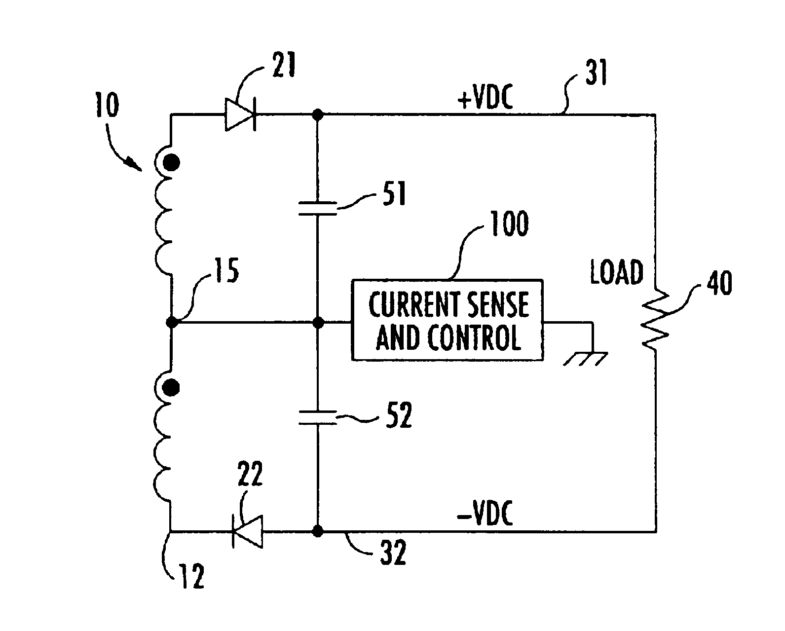
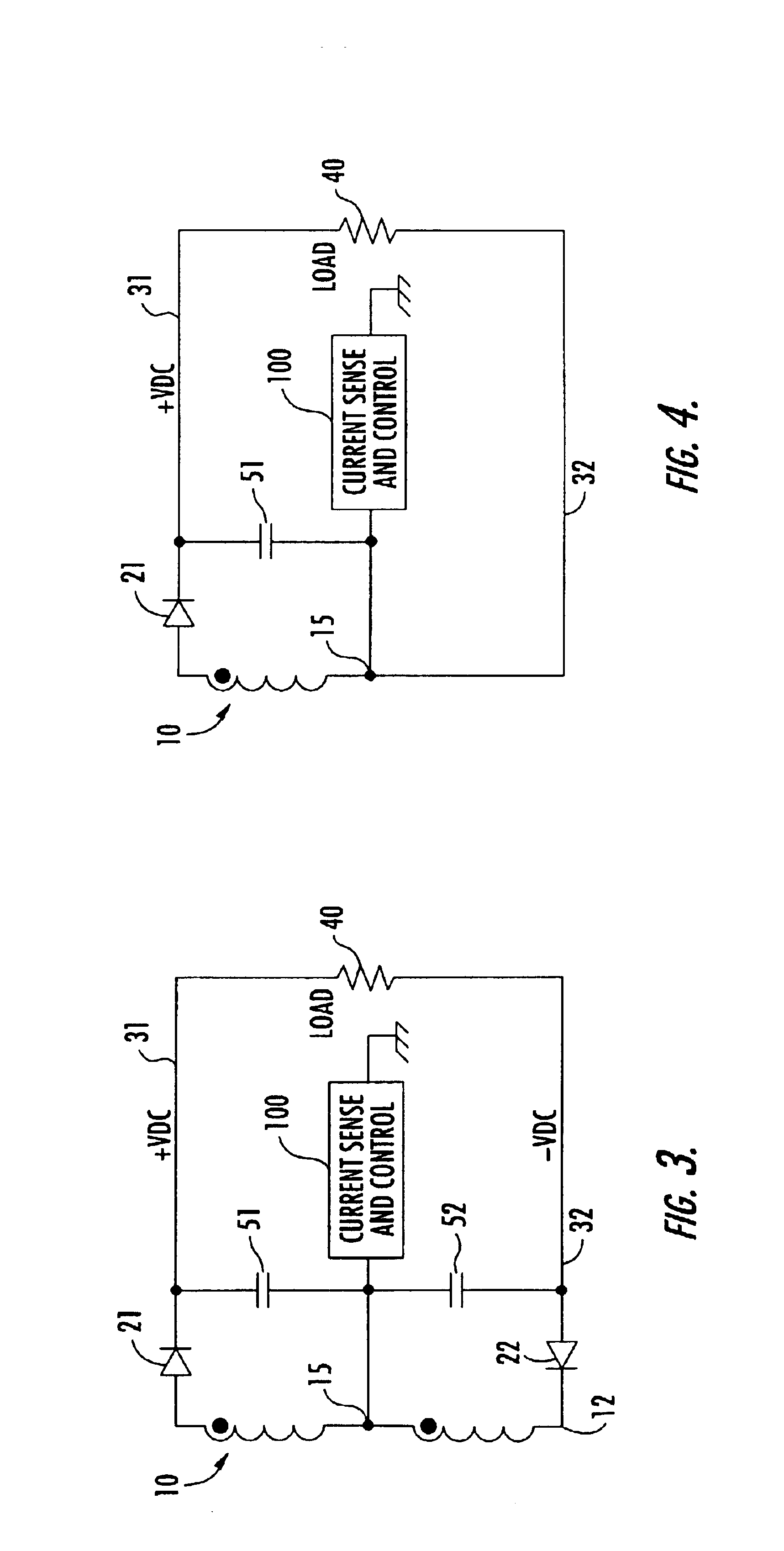
[0019]FIG. 5 schematically illustrates the control circuit 100 for the bipolar voltage generator architecture of FIG. 3. A ground fault current sense resistor 110 is coupled between the center tap 15 and ground. This effectively places the sense resistor in series with each of the two storage capacitors 51 and 52, between their associated (+) and (−) lines and ground. Coupled across the sense resistor 110 are a pair of complementary voltage-sensing transistors 120 and 130, output terminals of which are coupled in common to an output node 105. Although bipolar NPN devices are shown, it is to be understood that the invention is not limited thereto, but also may be implemented using alternative equivalent components, such as PNP transistors, or field effect transistors (FETs), for example.
[0020]To measure ground fault current associated with a ground fault to the positive (+) line 31, the NPN transistor 120 has its collector 121 coupled to output node 105, its base 122 coupled to the g...
second embodiment
[0025]FIG. 6 schematically illustrates the control circuit 100 for the bipolar voltage generator architecture of FIG. 3, in which the embodiment of FIG. 5 is augmented to include transient fault protection, and to improve noise immunity and sensitivity to longitudinal induction. In particular, for transient protection, the ground fault sense resistor 110 is coupled to the center tap 15 of output winding 10 by way of a surge-compensation resistor 115, and Zener diodes 116 and 117 are connected in series in an opposite polarity sense across the sense resistor 110. For noise immunity, the base 122 of transistor 120 is coupled through a resistor 124 to ground and through a (60 Hz) noise rejection capacitor 125 to its emitter 123.
[0026]Similarly, the base 132 of transistor 130 is coupled through a resistor 134 to the node between sense resistor 110 and resistor 115, and through a noise rejection capacitor 135 to its emitter 123. In addition, when it is intended that the control circuit b...
PUM
 Abstract
Description
Claims
Application Information