Hinges that are applied in the field are often installed under less than ideal conditions.
If this is not done, the door may potentially rub against the frame or drag on the threshold, increasing the difficulty for persons entering or leaving the building as well as imposing additional stress and wear on all of the door hardware, such as locksets and automatic door closers.
However, not all of the door alignment requirements are assured when the
doors and frames are manufactured.
Sometimes, particularly if the
doors and frames arrive at the job site from different manufacturing sources, the cutouts or recesses may not correspond, creating misalignment problems that can affect the operating clearances.
Also, the installation of frames can be affected by improperly dimensioned or misaligned wall openings, resulting in frame
distortion that contribute to door misalignment.
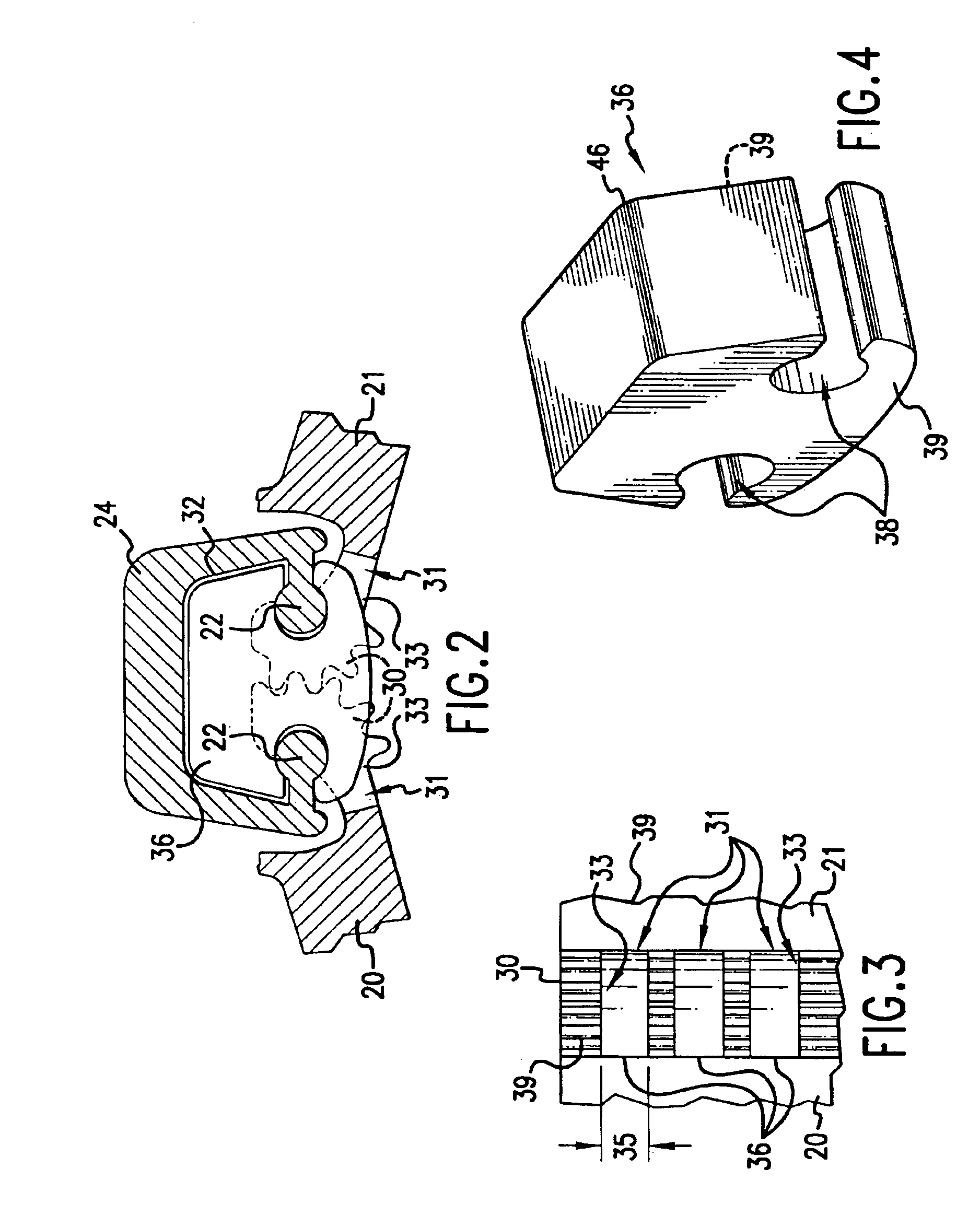
All too often, when transferring the new screw hole locations from the continuous hinge to the door and frame, the hinge can shift, or the
drill point can slide from the mark, contributing to poor door alignment when the installation is complete.
Such
fastener hole misplacements occur with even greater frequency when large holes are required for through-
bolting, especially when hidden internal door reinforcements are encountered by the installer.
It has been traditionally difficult to manufacture,
handle, and store the many hinge lengths required to properly fit a variety of
doors designed for architectural use.
Continuous hinges for these applications are subject to damage within the manufacturing environment because of the length and
fragility of their component parts and because of consequential damage to the completed
assembly during the various stages of shipment and transportation from the manufacturing site through the complex channels of distribution to the point of installation.
Packaging, shipping, and shipping damage costs can become high because of the unusual ratio of length-to-girth or width of the
package and the stringent requirements for protection against bending.
In addition, the inventory storage requirements for these long and fragile hardware items are costly, because they require specialized shelving or racks at every intermediate location.
Unlike conventional butt hinges, which are comprised of smaller, easier to
handle and cheaper parts, any such defect reduces or destroys the value of an inherently long continuous hinge part which can add substantially to the overall cost of manufacture.
While continuous hinges for very tall doors have sometimes been pieced together to form assemblies that are longer than any practical manufactured length, little attention has been paid to properly aligning these segments during installation so that the segments simulate the function of a single hinge.
Further complexity and cost results from the difficulty of maintaining adequate inventory of each and every required length suitable to the variety of door heights used in the
construction industry.
While it is possible to manufacture continuous hinges in virtually any reasonable length for large orders, the availability of unusual custom lengths is often subject to long delays and high costs at each step of the manufacturing and distribution cycle.
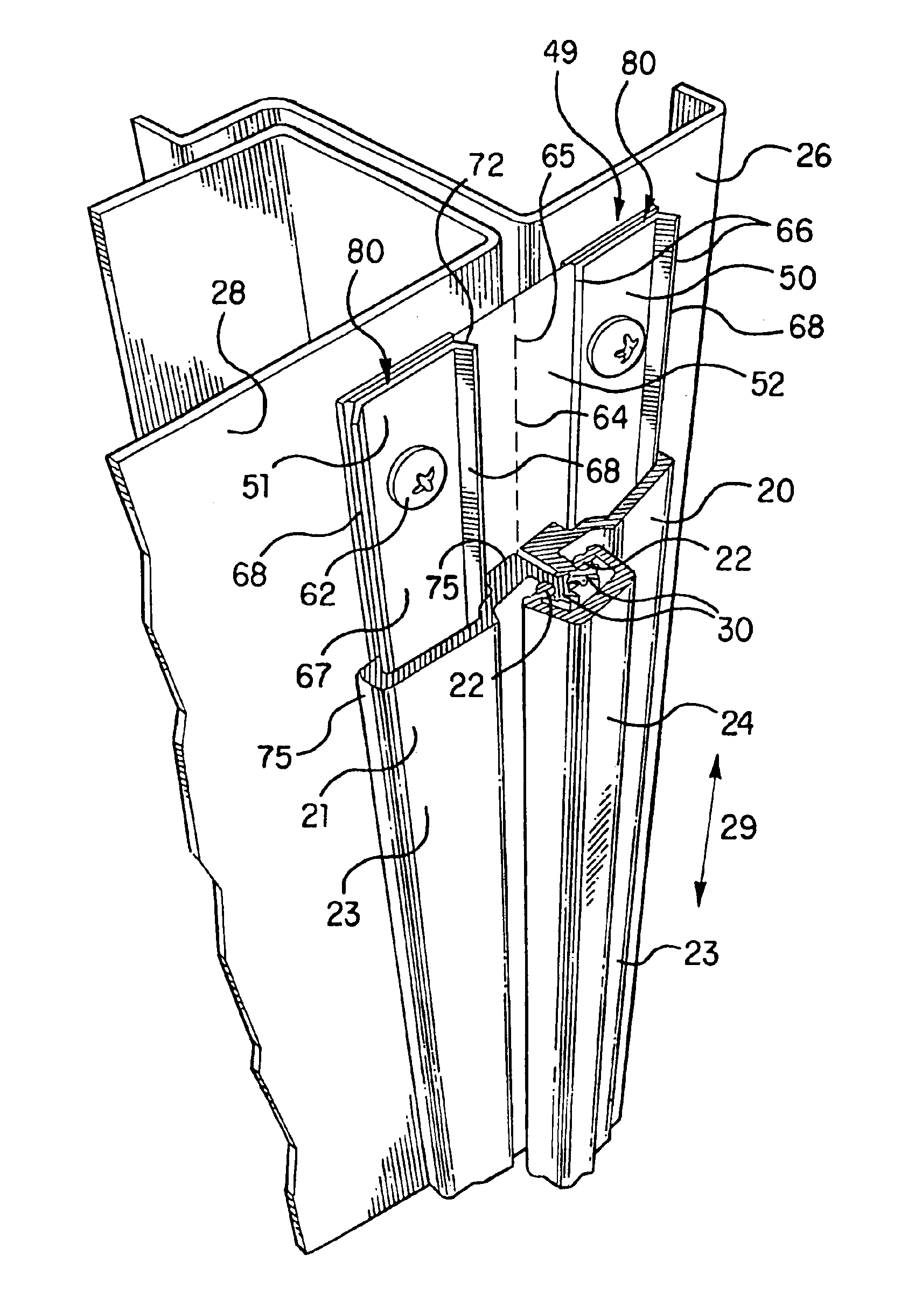
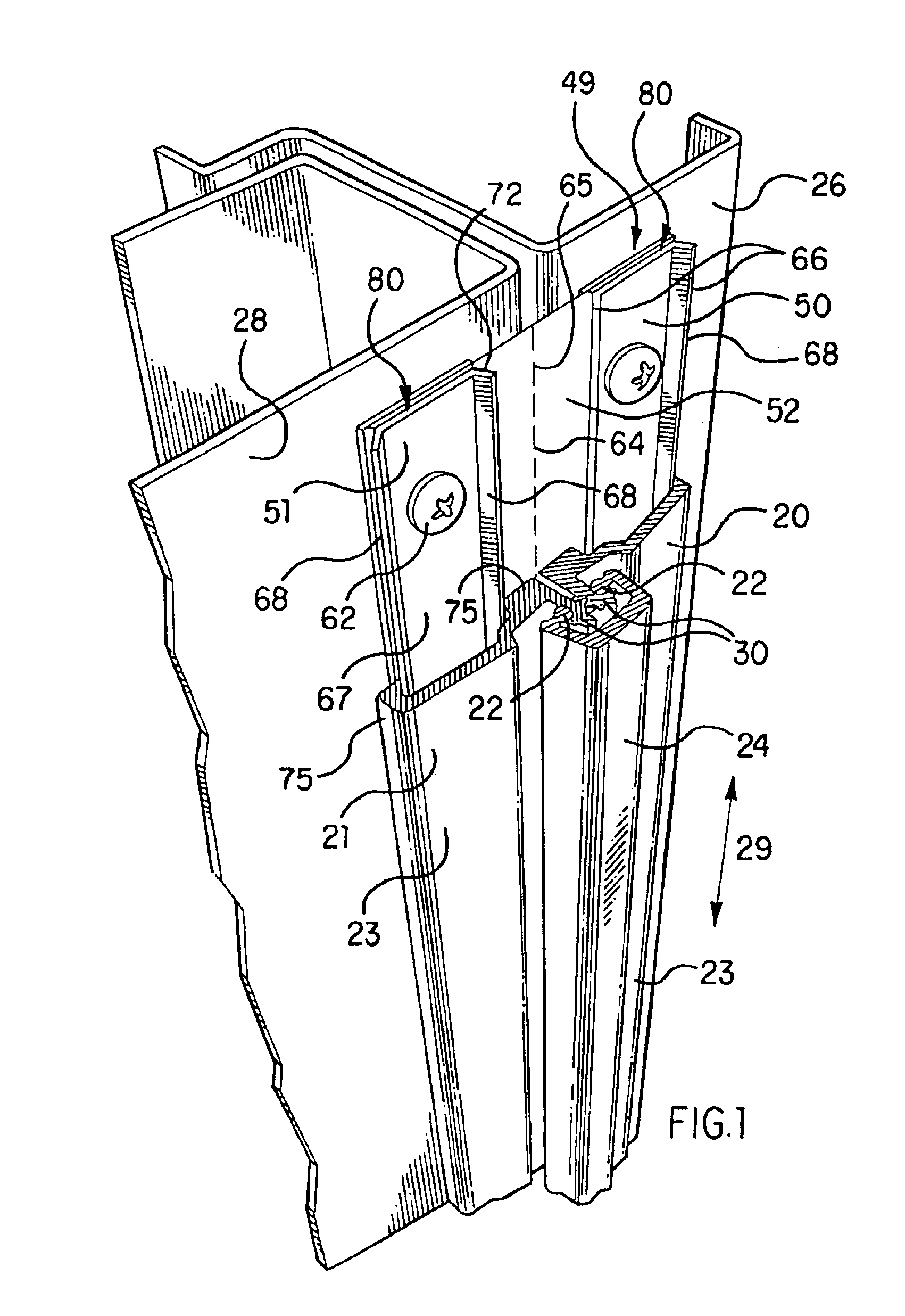
Also, one of the more difficult steps in continuous hinge installation in the field is the proper marking and preparation of the
fastener holes in a way which will insure the alignment of the door to its frame when the installation is complete.
While individual butt or mortise hinges are typically fitted into cutouts with pre-threaded bolt holes prepared in both the door and the frame at their respective factories, continuous hinges are more frequently applied to the unprepared surfaces of doors and frames which offer little to assist in their alignment.
Repair work in particular, where continuous hinges are used to overcome conditions in which conventional hinges have failed, is more dependent upon the
skill level of the installer because the
working environment as well as the condition of the door and frame components may be less than ideal, largely because the doors themselves may have suffered damage when their hinges failed and because the work must often be completed very quickly with a minimum of installation tools.
Unless all of the
fastener locations for a continuous hinge are carefully marked and drilled, the door will interfere with or rub against the frame following installation or shortly thereafter.

