

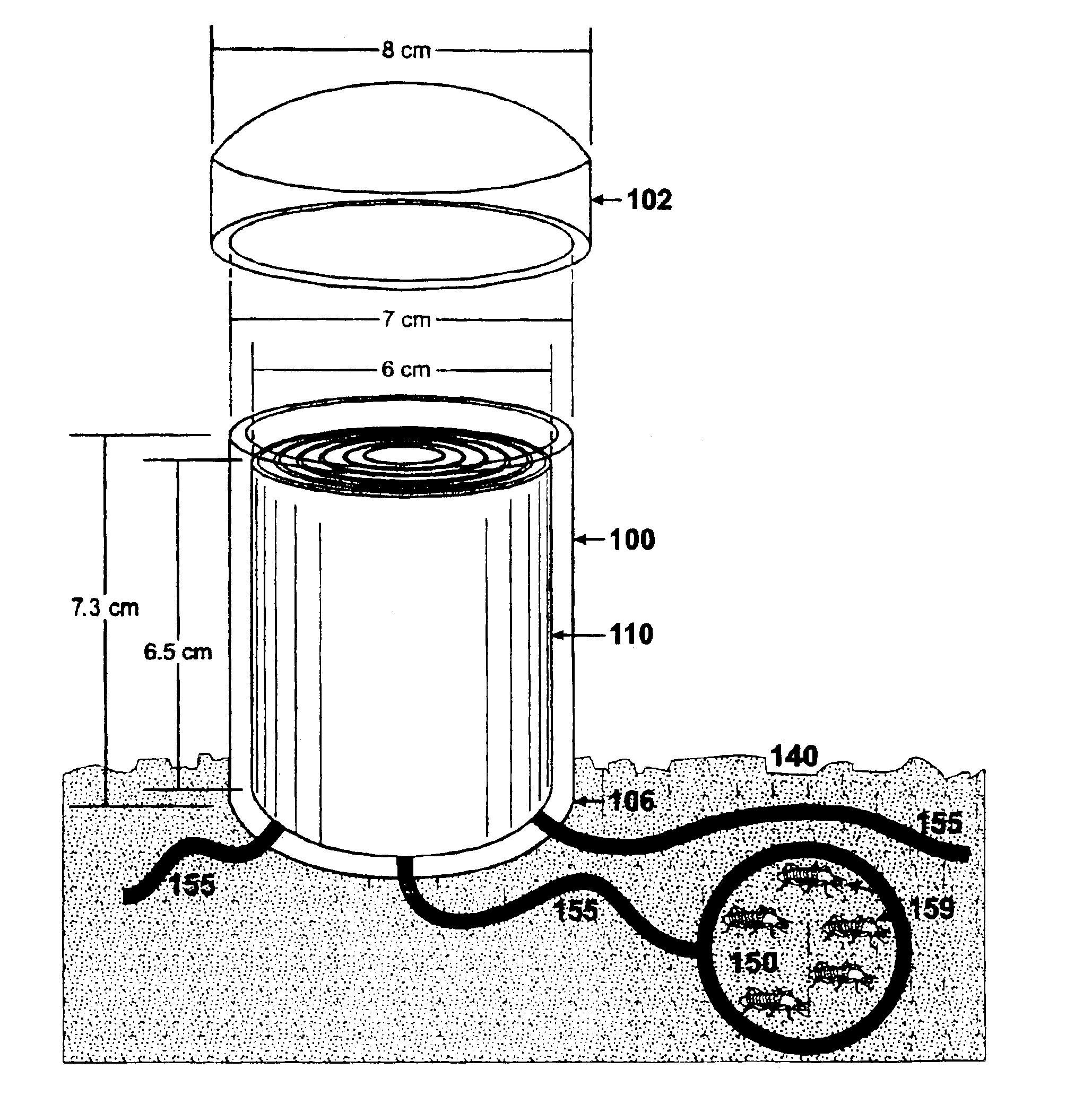
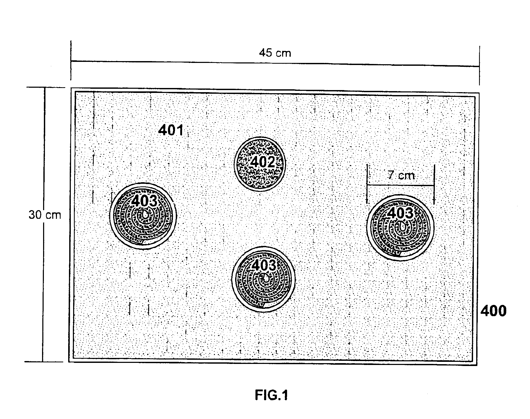
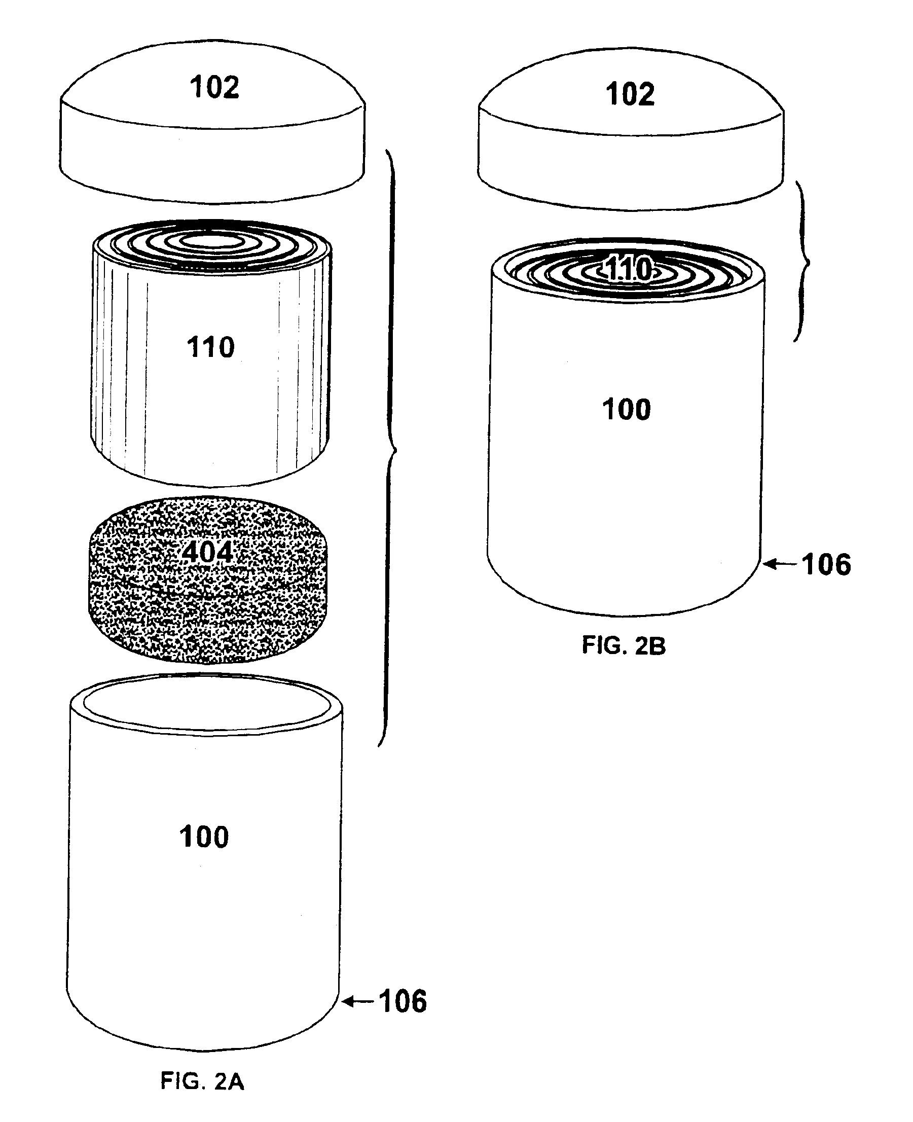
Alternating layer non-edible foraging matrix configurations for crawling arthropods
a technology of crawling arthropods and matrix configurations, which is applied in the direction of biocides, biocide, coatings, etc., can solve the problems of affecting the survival of crawling arthropods,
- Summary
- Abstract
- Description
- Claims
- Application Information
AI Technical Summary
Benefits of technology
Problems solved by technology
Method used
Image

Examples
first embodiment
[0055]The subject invention was tested recently at the USDA-ARS Center for Medical, Agricultural, and Veterinary Entomology, at Gainesville, Fla.
[0056]Data from two sets of experiments are included. In the first set of experiments, a total of 3,000 termites were used (2,970 workers and 30 soldiers) in all three replicates. In the second set of experiments, 3,000 termites were used in 4 replicates and 1,400 termites (1,386 workers and 14 soldiers) were used in two replicates for a total of six replicates. Fewer termites from 2 colonies were used because we could not collect enough to complete the replicates if a total of 3000 termites were used. The termites (Reticulitermes flavipes (Kollar)) were field collected from field colonies, separated from debris, and held in the laboratory at the USDA (United States Department of Agriculture) for no more than 14 days before introduction into a test arena for each experimental block. Termites from a different colony were used for each replic...
second embodiment
[0080]FIG. 6 is an exploded view of a second embodiment box application 500 of the subject invention. FIG. 7A is a perspective view of the second embodiment 500 of FIG. 6. FIG. 7B is a top view of the embodiment 500 of FIG. 7A along arrow B1. FIG. 7C is a bottom view of the embodiment 500 of FIG. 7A along arrow B2. FIG. 7D is a front view of the embodiment 500 of FIG. 7A along arrow B3. FIG. 7E is a side view of the embodiment 500 of FIG. 7A along arrow B4.
[0081]Referring to FIGS. 6 and 7A-7E, embodiment 500 can have a rectangular outer shape, having a first wall 510 and second wall 530 that can be sandwiched together with side perimeter members 522, 524, 526 all together forming a chamber space 540 therebetween. Walls 510, 530 and side perimeter members 522, 524, 526 can each be formed from an edible non-toxic food source such as wood, paper, cellulose material, foam, plastic, combinations thereof, and the like, that can be fastened together by for example, with a non-toxic adhesiv...
third embodiment
[0092]FIG. 8 is an exploded view of a third embodiment 600 of the invention. FIG. 9A is a top view of the main outer housing 605 of FIG. 8 along arrow C1. FIG. 9B is a bottom view of the embodiment 600 of FIG. 8 along arrow C2. FIG. 9C is a front view of the embodiment 600 of FIG. 8 along arrow C3. FIG. 9D is a side view of the embodiment 600 of FIG. 8 along arrow C4.
[0093]Referring to FIGS. 8 and 9A-9D, embodiment 600 includes a main housing 605 having a front wall 610, back wall 630 and side perimeter members 622, 624, 626 sandwiched there between and that forms a chamber 640 inside accessible by an upper opening 642. Walls 610, 630 and side perimeter members 622, 624, 626 can each be formed from an edible non-toxic food source such as wood, paper, cellulose material, foam, plastic, combinations thereof, and the like, that can be fastened together by for example, with a non-toxic adhesive such glue, and the like. For example, main housing chamber 605 can have walls 610, 630 formed...
PUM
| Property | Measurement | Unit |
|---|---|---|
| inner diameter | aaaaa | aaaaa |
| inner diameter | aaaaa | aaaaa |
| inner diameter | aaaaa | aaaaa |
Abstract
Description
Claims
Application Information