Hydraulic power steering system utilizing fuel as a working fluid

a technology of working fluid and hydraulic power steering, which is applied in the direction of liquid fuel feeders, machines/engines, etc., can solve the problems of increasing maintenance expenses and warranty costs, and affecting the operation of the system. , to achieve the effect of reducing overheating and effective cooling of fuel

Inactive Publication Date: 2005-08-16
R H SHEPPARD
View PDF6 Cites 13 Cited by
  • Summary
  • Abstract
  • Description
  • Claims
  • Application Information

AI Technical Summary

Benefits of technology

[0007]The present invention is an improved hydraulic power steering system that utilizes vehicle fuel as the working fluid. The fuel is preferably stored in a conventional fuel tank outside of the engine compartment. The fuel tank effectively cools the fuel and eliminates overheating. Oil coolers, water coolers, and extra hosing often used to provide additional cooling in conventional power steering systems are eliminated.
[0009]A return line returns the fuel from the steering gear to the fuel tank. A truck fuel tank is much larger than a conventional power steering fluid reservoir. The tank is located outside of the engine compartment, exposed to the wind stream generated by truck movement. The size and location of the fuel tank enables the tank to function as an effective heat sink or radiator that cools fuel stored in the tank.
[0011]In addition to eliminating overheating and the need to locate a steering fluid reservoir within the engine compartment, power steering systems in accordance with the present invention have a number of additional advantages. The cost of the power steering supply reservoir is eliminated. The cost of power steering fluid is also eliminated, as is the need to change power steering fluid and dispose of the used fluid in an environmentally responsible manner. Each time the fuel tank is filled, fresh working fluid for the power steering system is also provided.

Problems solved by technology

If overheated power steering fluid is circulated through the steering system, pressure seals in the system may be damaged.
Replacing damaged seals increases maintenance expenses and warranty costs.
As air pollution requirements for trucks become increasingly restrictive, engine temperatures are increasing.
It is becoming more difficult to place the power steering reservoir in a location that provides adequate cooling.
Furthermore, as the engine compartment becomes more crowded, finding a suitable location for the reservoir becomes even more difficult.

Method used


Image

  • Hydraulic power steering system utilizing fuel as a working fluid
  • Hydraulic power steering system utilizing fuel as a working fluid
  • Hydraulic power steering system utilizing fuel as a working fluid

Examples


Embodiment Construction

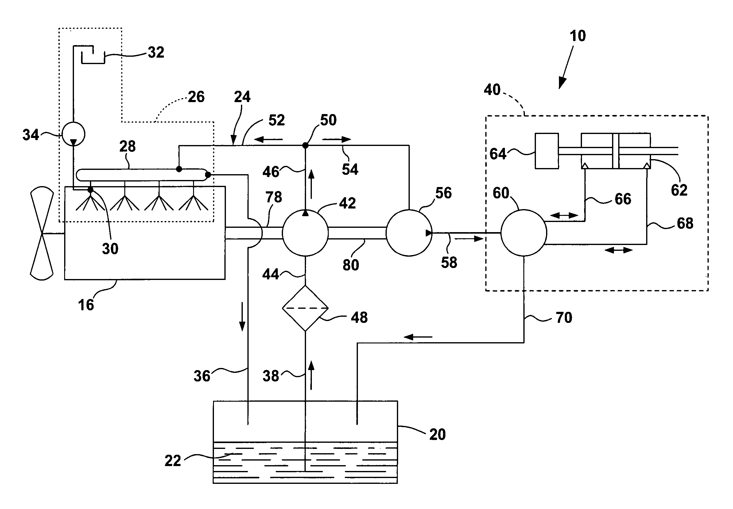
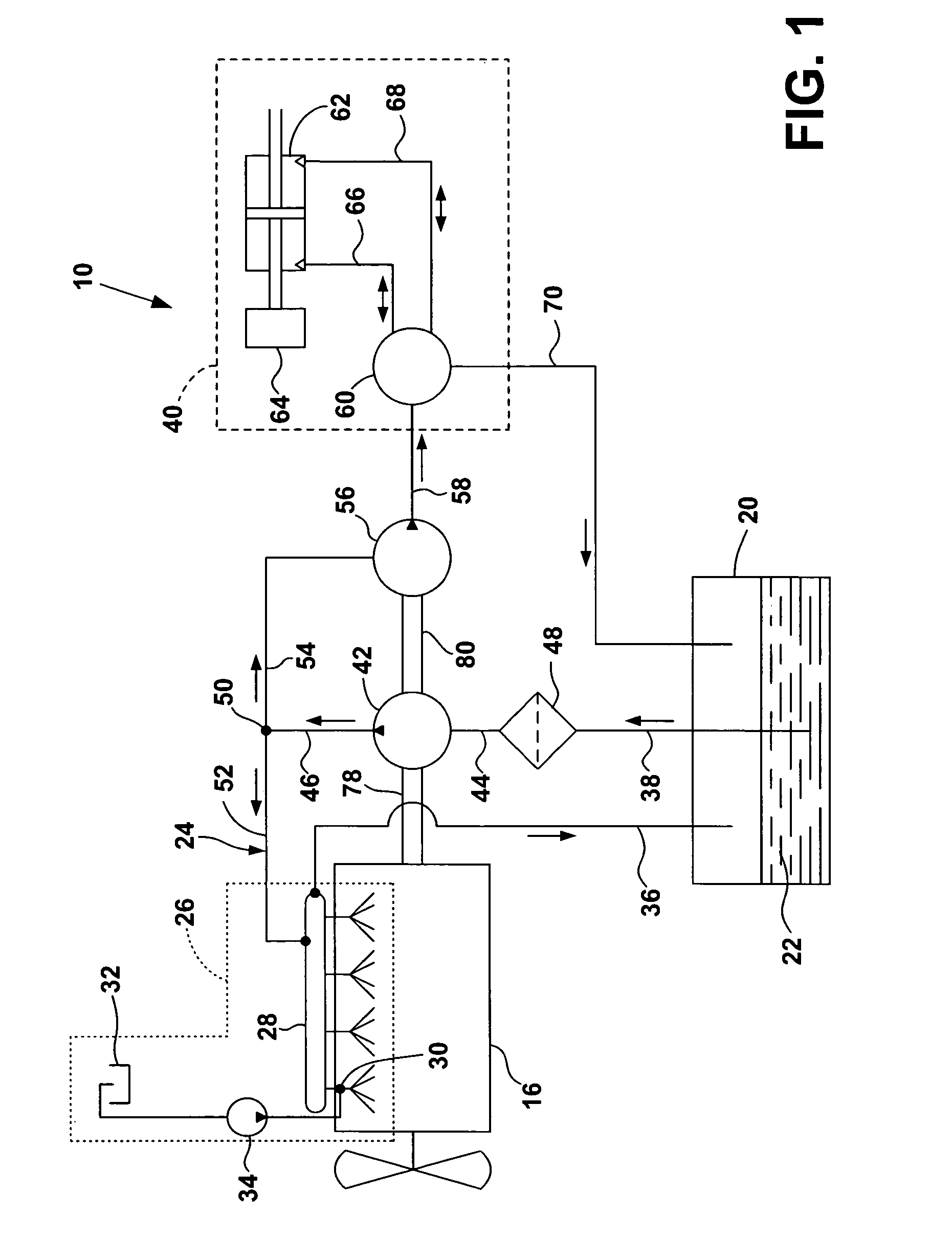
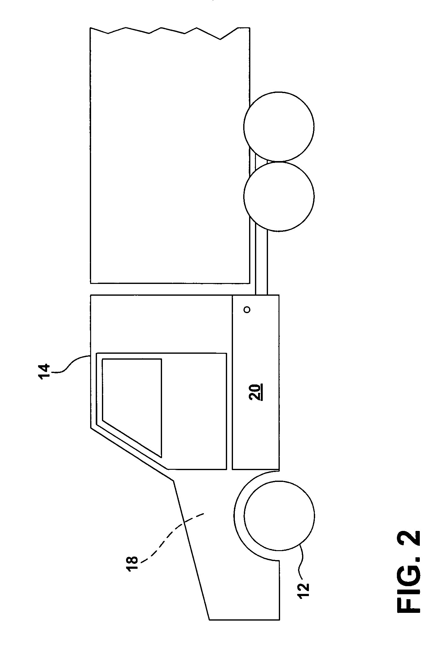
[0017]FIGS. 1 and 2 illustrate a hydraulic power steering system 10 in accordance with the present invention. Power steering system 10 turns the steerable wheels 12 of a heavy duty, over-the-road truck 14. Truck 14 is equipped with a diesel engine 16 located within engine compartment 18. A fuel tank 20 outside of the engine compartment contains a reservoir of diesel fuel 22. The capacity of fuel tank 20 is 300 gallons, a conventional size for a large truck.

[0018]Fuel system 24 flows fuel from fuel tank 20 to engine 16. In the illustrated embodiment fuel system 24 includes a conventional common rail fuel injection system 26 that injects fuel into the engine for combustion. An accumulator 28 serves as a common rail, receiving fuel and forming a common supply for a number of fuel injectors 30. The injectors are actuated by fluid from a supply reservoir 32 (flow to only one injector is shown in FIG. 1) pressurized by a high-pressure injection pump 34. The actuator fluid can be diesel fu...


PUM


Abstract

A hydraulic power steering system for a diesel-fueled truck utilizes vehicle fuel as a working fluid. The steering system includes a power steering gear connected to the steerable wheels of the truck. A first pump flows fuel from the truck's fuel tank to both the steering gear and to the engine. A second pump increases the pressure of the fluid to the steering gear to provide power assist. The flow to the steering gear returns to the fuel tank for recirculation.

Description

BACKGROUND OF THE INVENTION[0001]The invention relates to a hydraulic power steering system for turning the steerable wheels of a vehicle.[0002]Heavy-duty trucks use a hydraulic power steering system to provide power assist in turning the steerable wheels of the truck.[0003]A conventional hydraulic power steering system includes a pump that flows high-pressure working fluid to a fluid motor. Power steering fluid is utilized as the working fluid. Power steering fluid is a specialized hydraulic oil supplied from a reservoir located within the engine compartment. The fluid is continuously recirculated through the system and may be replaced at regularly-scheduled maintenance intervals.[0004]A major concern with hydraulic power steering systems is heat. The power steering reservoir is heated by its close proximity to the engine. If overheated power steering fluid is circulated through the steering system, pressure seals in the system may be damaged. Replacing damaged seals increases main...

Claims


Application Information

Patent Timeline
Patent Type & Authority Patents(United States)
IPC IPC(8): F02M37/00
CPCF02M37/0023F02M37/0047
Inventor SHEPPARD, PETER H.
Owner R H SHEPPARD
Why Eureka
Try Eureka