Charged-particle beam instrument and method of correcting aberration therein

a charged particle and instrument technology, applied in the direction of instruments, beam deviation/focusing by electric/magnetic means, heat measurement, etc., can solve the problems of insufficient consideration of the stability of the aberration correction system and the range of applied voltage and even the optimum conditions, and the spherical aberration-correcting potential becomes too large, and achieves less noise.

Active Publication Date: 2005-08-16
JEOL LTD
View PDF1 Cites 8 Cited by
  • Summary
  • Abstract
  • Description
  • Claims
  • Application Information

AI Technical Summary

Benefits of technology

[0026]It is an object of the present invention to provide a method of correcting aberrations in a charged-particle beam instrument stably and optimally in such a way that the instrument is less affected by noise, is free of the withstand voltage problem of the instrument at high accelerating voltages, and is free of the problem with corrective potentials at low accelerating voltages. It is another object to provide a charged-particle beam instrument.

Problems solved by technology

From a point of view of practicability, however, it can be said that sufficient consideration has not been given to the stability of the aberration correction system and to the range of the applied voltage and even to the optimum conditions.
Thirdly, where an aberration-correcting potential proportional to the accelerating voltage is used as in the prior art example, if the instrument is made immune to noise components at low accelerating voltages, it is necessary to reduce the amount of noise component of the voltage or current of the power supply to a practical value. If this is achieved, the instrument is expensive to make.
Fourthly, if the resultant magnification MR of the aberration corrector and objective lens is adjusted to maintain constant the excitation current through the magnetic quadrupole components for correcting chromatic aberration, the aberration-correcting potential is non-relativistically in proportion to the square root of the accelerating voltage. This alleviates the first through third problems described above. However, where the range of the variable accelerating voltage is wide, the spherical aberration-correcting potential becomes too large at low accelerating voltages. As a result, an expensive power supply may be necessary.
Fiftly, complex data for correcting spherical aberration has been necessary for each value of the accelerating voltage and for each value of the working distance.

Method used


Image

  • Charged-particle beam instrument and method of correcting aberration therein
  • Charged-particle beam instrument and method of correcting aberration therein
  • Charged-particle beam instrument and method of correcting aberration therein

Examples


Embodiment Construction

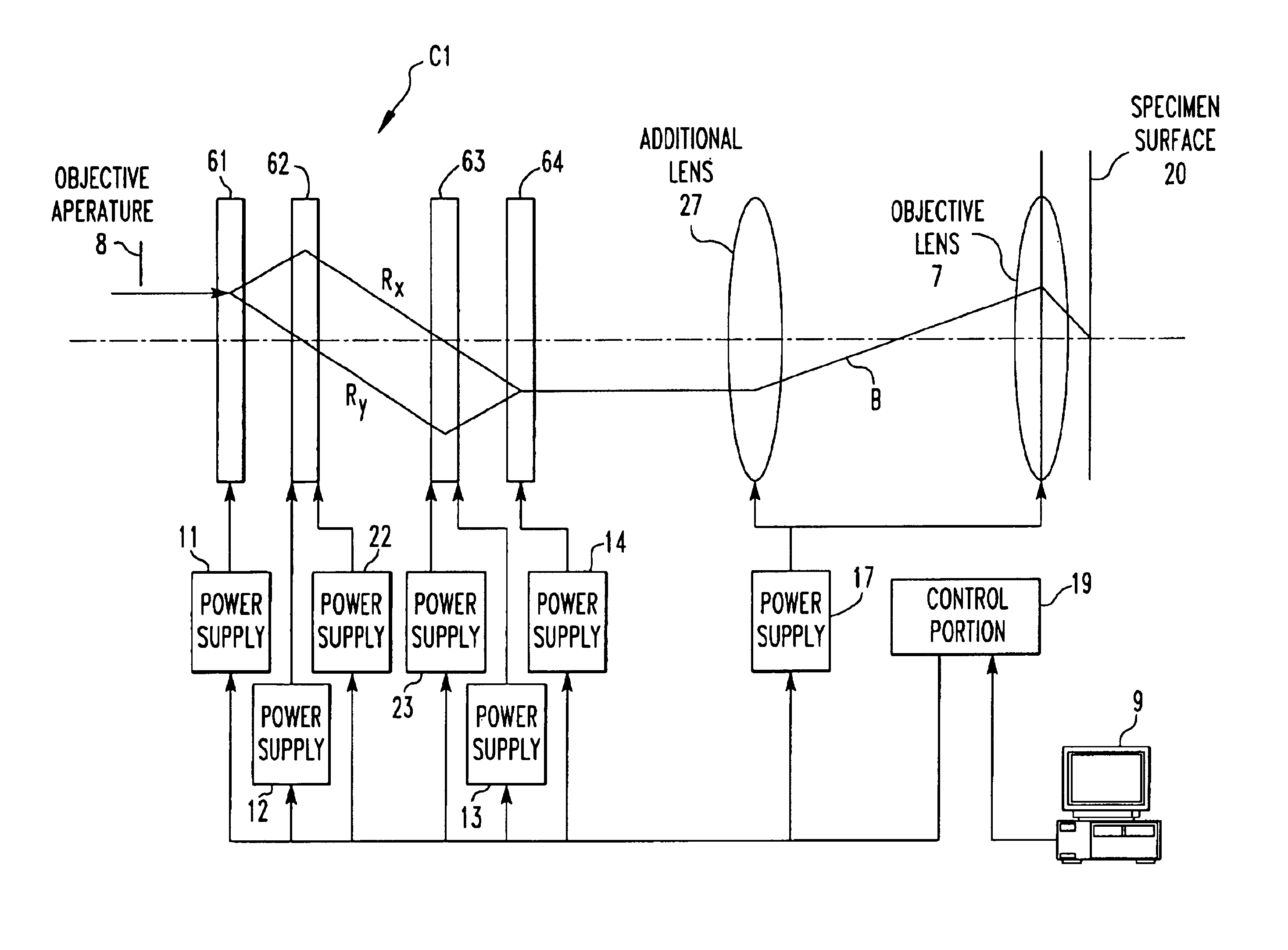
[0042]The preferred embodiments of the present invention are hereinafter described in detail with reference to the drawings. FIG. 5 shows the fundamental structure of the present invention. An instrument for directing a part of a beam of charged particles as a probe at a specimen is shown. The instrument is fitted with an aberration corrector C1 for correcting chromatic aberration in the same way as in the past. The corrector C1 is made up of four stages of multipole units (hereinafter may be referred to as the multipole elements) 61, 62, 63, and 64 acting as aberration correction units. Of these four stages of multipole elements 61-64, the two central stages of multipole elements 62 and 63 are designed to function as magnetic multipole elements capable of superimposing a magnetic potential distribution analogous to an electric potential distribution created by electrostatic multipole element-activating electric potentials on the electric potential distribution.

[0043]The first and f...


PUM


Abstract

An aberration correction method and charged-particle beam instrument with four stages of multipole units. The two central stages of multipole units function as two stages of magnetic quadrupole components for superimposing a magnetic potential distribution analogous with an applied electric potential distribution on this electric potential distribution. The instrument further includes an objective lens, an objective aperture mounted in the optical path for a beam of charged particles, an operation portion for varying the accelerating voltage or the working distance between the objective lens and a specimen, and a control portion for controlling the multipole units according to an operation of the operation portion. When the accelerating voltage or working distance is varied, the resultant magnification of the four stages of multipole units and objective lens mounted behind the units is adjusted to maintain constant at least one of octupole component-activating potentials for correcting third-order aperture aberrations.

Description

BACKGROUND OF THE INVENTION[0001]1. Field of the Invention[0002]The present invention relates to a method of correcting chromatic and spherical aberrations in a charged-particle beam instrument, such as an electron beam instrument (e.g., a scanning electron microscope) or an ion beam instrument (e.g., an ion microprobe). The invention also relates to such a charged-particle beam instrument.[0003]2. Description of Related Art[0004]The following non-patent references appear to be relevant to the present invention: (1) H. Rose, Optik 33, Heft 1, pages 1-24 (1971); (2) J. Zach, Optik 83, No. 1, pages 30-40 (1989); (3) J. Zach and M. Haider, Nucl. Instr. and Meth. In Phys. Res. A 363, pages 316-325 (1995); and (4) M. Haider et al., Optik 63, No. 1, pages 9-23 (1982).[0005]In scanning electron microscopes and transmission electron microscopes, an aberration corrector is incorporated in the electron optics in order to achieve high-resolution imaging or enhance the probe current density. In...

Claims


Application Information

Patent Timeline
Patent Type & Authority Patents(United States)
IPC IPC(8): H01J37/153H01J37/04
CPCH01J37/153
Inventor MATSUYA, MIYUKIUNO, SHINOBU
Owner JEOL LTD
Why Eureka
Try Eureka