
System and method for traffic management control in a data transmission network

a data transmission network and traffic management technology, applied in data switching networks, frequency-division multiplexes, instruments, etc., can solve problems such as data loss, device simply clogging and ceased to function properly, and transactions not completed

Inactive Publication Date: 2005-08-16
TREND MICRO INC
View PDF28 Cites 27 Cited by
  • Summary
  • Abstract
  • Description
  • Claims
  • Application Information

AI Technical Summary

Benefits of technology

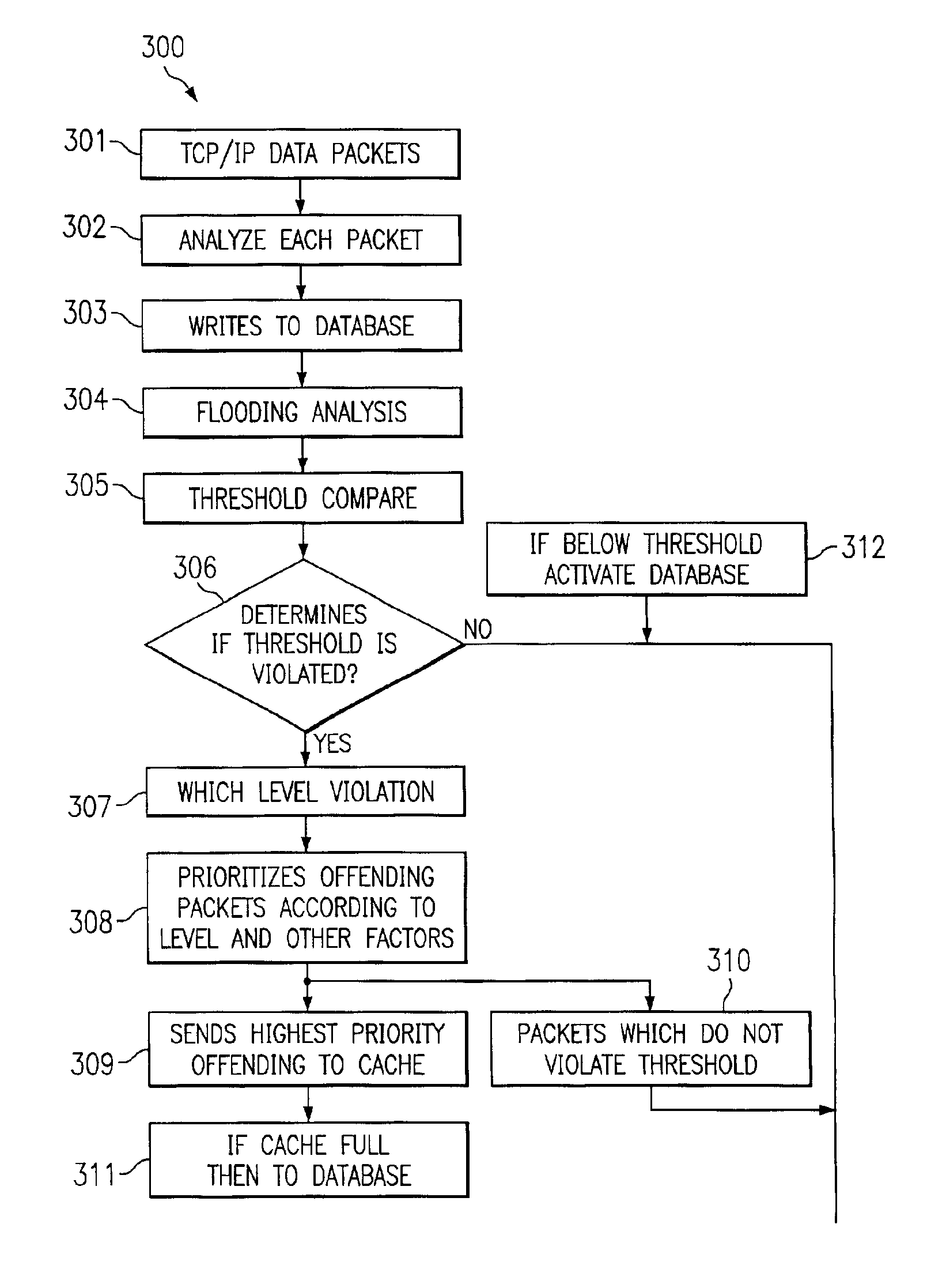
[0008]The present invention includes a system which implements a three tiered architecture where the database runs on one computer, or across multiple computers, and the kernel and all of its intelligence runs on a separate computer while the applications and management tools run on other computer(s). The system is designed to monitor every tcp / ip packet directed toward a company and to keep track of each packet from each IP address, including all of the bytes of information associated with each packet. The goal of the system and method is to prevent flooding which is defined as a threshold above which data throughput must not go.
[0010]Generally, when it comes to flooding, there are four (or more or less) threshold levels which exist which are percentages of the total maximum band-width of the network. The thresholds can be for example 20, 30, or 40 percent of maximum. If the traffic flow is under the lowest threshold, everything runs smoothly. Once the number of arriving packets and accumulated bytes violate a threshold, the system begins, automatically, the process of choking or holding certain packets. If higher thresholds are violated then more and more severe action is taken, i.e. more and more packet(s) are prevented from flowing through the system.

Problems solved by technology

When this data flow is interrupted, even for the briefest of intervals, a major problem exists.
One way to interrupt such data flow is by flooding any communication line (or any network device on the pathway) with so many data packets that the device simply clogs and ceases to function properly.
In such a situation, data can be lost, transactions not completed and the flow of commerce halted.
This, of course, presupposes that the operator even knows which sending IP address(es) is causing the problem.
If the rogue sending address keeps changing, the operator (system administrator) is at a loss.
The problem with the solutions to date is the fact that by the time a human can respond to the existing condition, it is already beyond his / her ability to control the traffic and the network is brought down by the intruding traffic overload.
For example, today even assuming a modest speed of, let's say a 1,000 packet / second, about half of the maximum data rate of a T1 channel, the human eye cannot respond that fast to read the IP addresses, digest the information and act before many, many packets enter the system and cause damage.
Such large numbers of packets, when backed up, cause the system to stop functioning.

Method used


Image

  • System and method for traffic management control in a data transmission network
  • System and method for traffic management control in a data transmission network
  • System and method for traffic management control in a data transmission network

Examples


Embodiment Construction

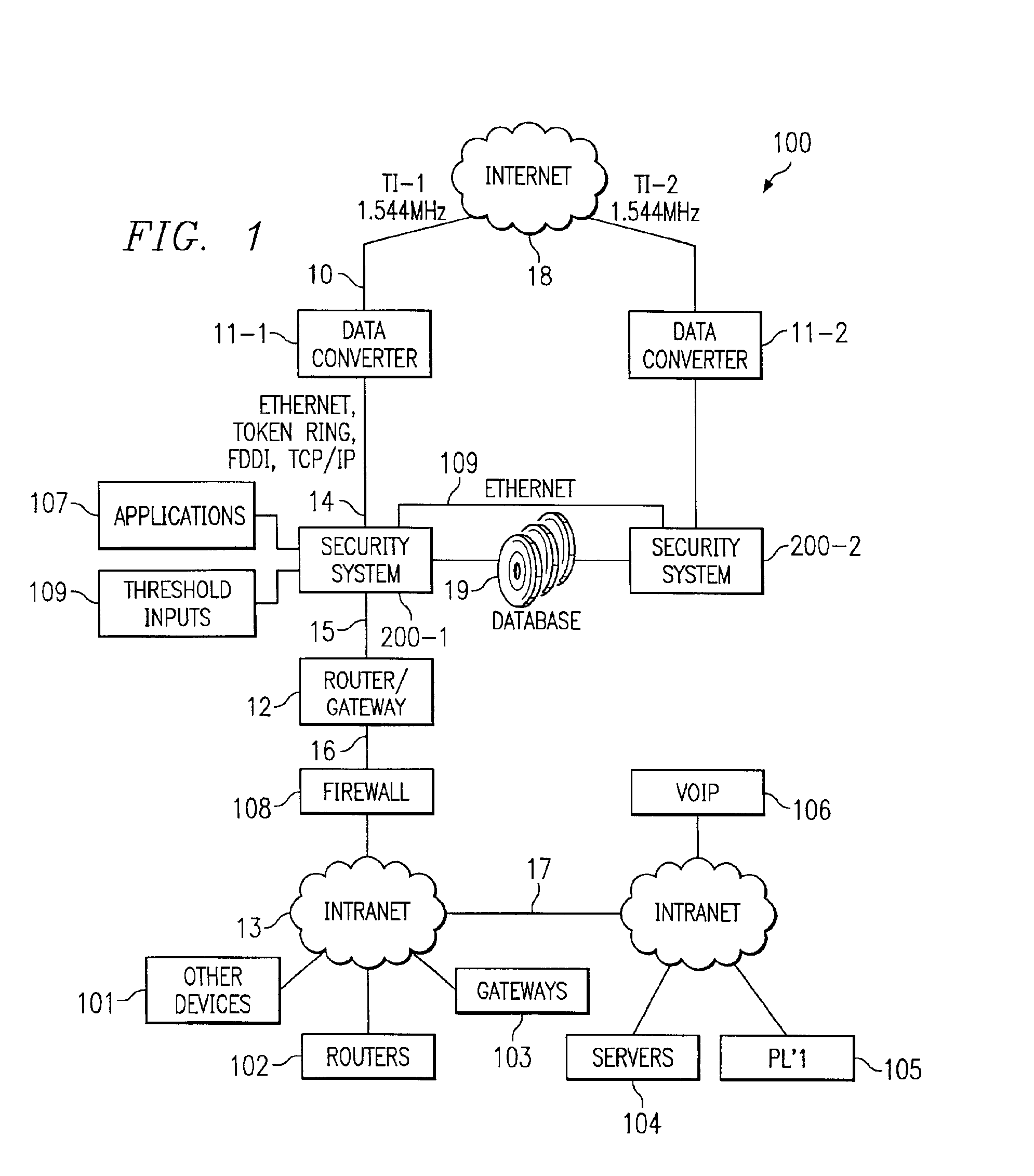
[0019]Turning now to FIG. 1, as packets come from internet 18 (or any source), they travel to data converter 11-1 (11-2) through line 10, which could be a T1, T3, OC48 or any other communication media. Data converter 11-1 can be several data converters which take the data packets off the line and convert that data to an “internal” protocol, such as token ring, FDDI, TCP / IP or other protocol desired by an enterprise. These packets then pass to security system 200-1 one medium 14. When the packets arrive at security system 200-1, each packet will be analyzed, as will be discussed hereinafter. Only those medium packets which make their way through security system 200-1 are delivered to router 12 over 15. Router 12 could be a combination router / gateway or, in fact, router 12 and / or firewall 108 could be built directly into security system 200-1 if so desired.

[0020]Those packets that manage to make it through security system 200-1 are delivered to enterprise internal (intra) network 13, ...


PUM


Abstract

A traffic management system sniffs data arriving at any point in a system. The sniffer operates to remember certain parameters pertaining to the data. When the amount of data arriving at the point begins to reach a critical level (usually dependent upon data processing capability associated with that point), the system begins to remove (and share) subsequent arriving data based, in part, upon the remembered parameters of recently received data. Data that is stored is returned to the system when the critical threshold recedes.

Description

RELATED APPLICATIONS[0001]This application is a Continuation in Part of U.S. patent application Ser. No. 09 / 572,112 filed May 17, 2000 and entitled “Intelligent Feedback Loop Process Control System,” which is herein by reference.TECHNICAL FIELD[0002]This invention relates to data network control systems and more particularly to a system and method for monitoring and filtering traffic to maintain a constant stream of data flowing in and / or out of a particular location.BACKGROUND[0003]Data flow in and out of a data source is vital to the proper operation of many enterprises. When this data flow is interrupted, even for the briefest of intervals, a major problem exists. One way to interrupt such data flow is by flooding any communication line (or any network device on the pathway) with so many data packets that the device simply clogs and ceases to function properly. In such a situation, data can be lost, transactions not completed and the flow of commerce halted.[0004]Companies are ge...

Claims


Application Information

Patent Timeline
IPC IPC(8): H04L12/26H04L29/06H04L12/24H04L12/66
CPCH04L12/2602H04L43/00H04L63/02H04L63/0428H04L63/12H04L63/1408H04L63/1416H04L63/1425H04L63/1441H04L63/1458H04L63/1466H04L43/06H04L43/0817H04L43/0882H04L43/0888H04L43/16H04L43/18H04L63/0227
Inventor SHARP, CLIFFORD F.DARK, SUSAN PITTMAN
Owner TREND MICRO INC
Learn More