
Low noise, low distortion, muxable Gilbert mixer signal processing system and method with AGC functionality

a gilbert mixer and function technology, applied in the field of electronic circuits and systems, can solve the problems of order intercept, difficult power, difficult for a single radio frequency (rf) switch to cover either the rf, etc., and achieve the effect of reducing insertion loss and wide band operation

Inactive Publication Date: 2005-08-16
MICROELECTRONICS TECH INC
View PDF13 Cites 29 Cited by
  • Summary
  • Abstract
  • Description
  • Claims
  • Application Information

AI Technical Summary

Benefits of technology

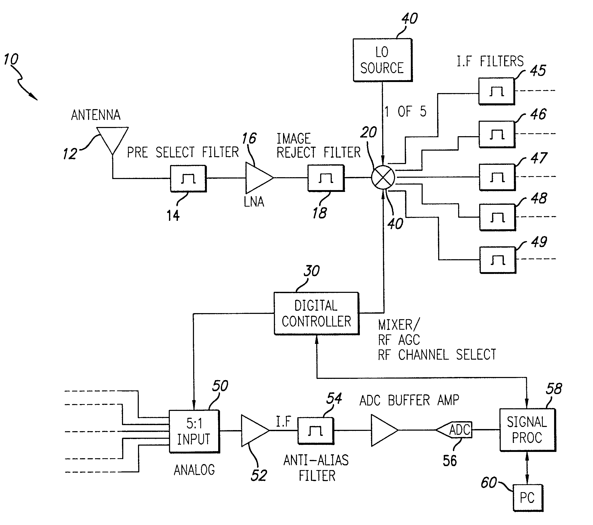
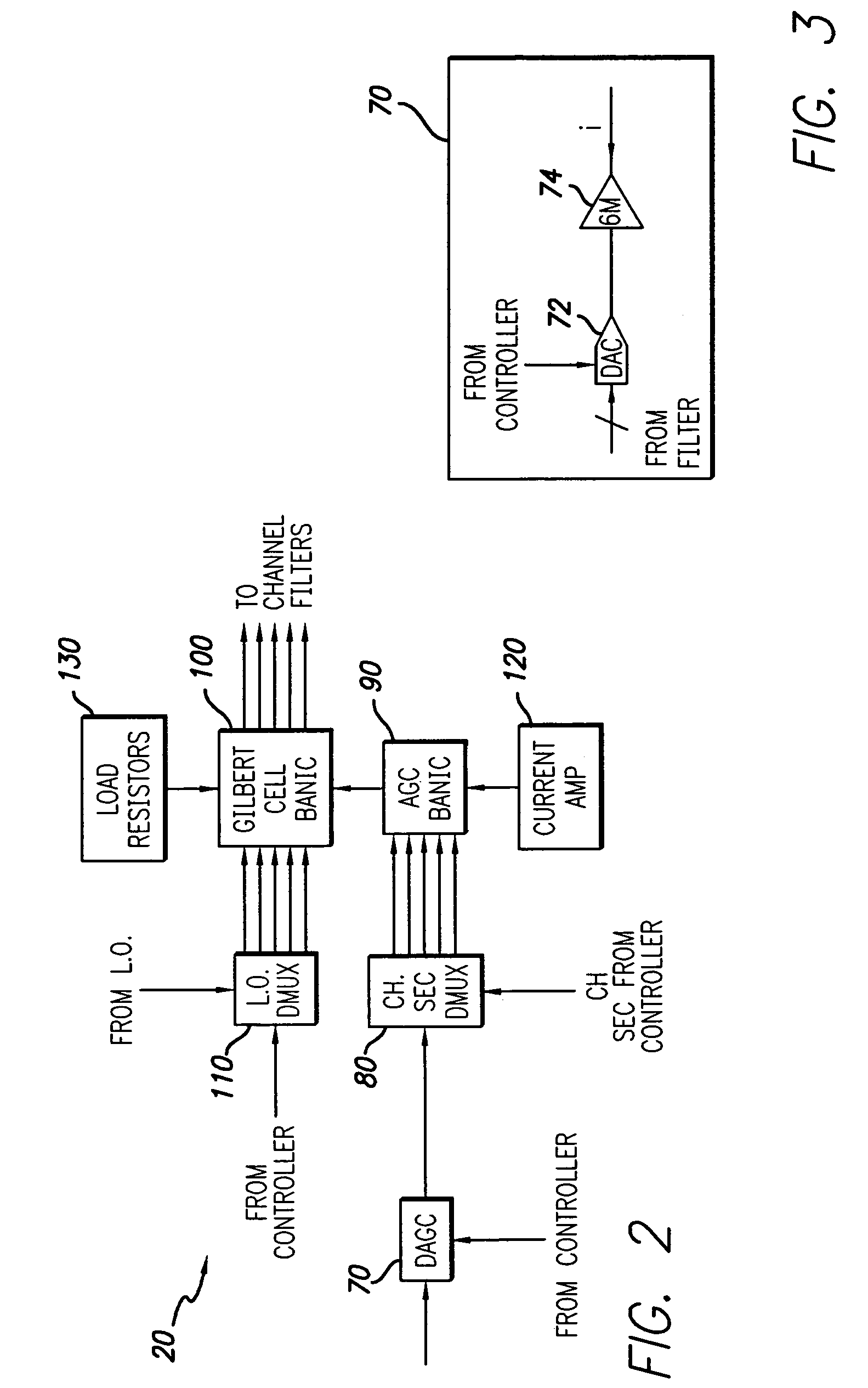
[0010]In a specific illustrative embodiment, the system further includes a radio frequency stage for downconverting a received signal and providing the input signal in response thereto. In the specific embodiment, the first circuit includes a mixing circuit. The mixing circuit includes Gilbert cells and circuitry for providing automatic gain control for each of the channels individually. The Gilbert cells and the automatic gain control circuitry are driven by a transconductance amplifier and therefore operate in a current mode. Differential digital automatic gain control signals are provided in response to a channel select signal from a digital control circuit. The inventive circuit provides multiple IF channels which may be filtered individually. The invention thereby provides wide band operation in a simple low power single stage while the current mode thereof is effective in the reduction of insertion loss.

Problems solved by technology

However, it would be difficult for a single radio frequency (RF) switch to cover either the RF or IF frequency range.
Unfortunately, in addition to requiring complicated circuitry, this approach would present difficult power, third order intercept (intermodulation product distortion), noise figure, insertion loss and interchannel isolation issues.
In addition, the switches would have to operate over a wide RF band or a wide IF band, both of which are difficult to achieve.

Method used


Image

  • Low noise, low distortion, muxable Gilbert mixer signal processing system and method with AGC functionality
  • Low noise, low distortion, muxable Gilbert mixer signal processing system and method with AGC functionality
  • Low noise, low distortion, muxable Gilbert mixer signal processing system and method with AGC functionality

Examples


Embodiment Construction

[0019]Illustrative embodiments and exemplary applications will now be described with reference to the accompanying drawings to disclose the advantageous teachings of the present invention.

[0020]While the present invention is described herein with reference to illustrative embodiments for particular applications, it should be understood that the invention is not limited thereto. Those having ordinary skill in the art and access to the teachings provided herein will recognize additional modifications, applications, and embodiments within the scope thereof and additional fields in which the present invention would be of significant utility.

[0021]FIG. 1 is a block diagram of an illustrative implementation of a receiver incorporating the signal processing system of the present invention. The system 10 includes an RF front end comprising an antenna 12, a conventional preselect filter 14, a low noise amplifier (LNA) 16 and an image rejection filter 18. The preselect filter 14 narrows the r...


PUM


Abstract

A signal processing system and method. The inventive system includes a first circuit for distributing an input signal between two or more channels in a current mode of operation. A second circuit is disposed in each of the channels for processing the input signal and providing an output signal in response thereto. A third circuit is provided to combine the signals output by the processing circuit. A fourth circuit is included for controlling the first and the third circuits. In a specific illustrative embodiment, the system further includes a radio frequency stage for downconverting a received signal and providing the input signal in response thereto. In the specific embodiment, the first circuit includes a mixing circuit. The mixing circuit includes Gilbert cells and circuitry for providing automatic gain control for each of the channels individually. The Gilbert cells and the automatic gain control circuitry are driven by a transconductance amplifier and therefore operate in a current mode. Differential digital automatic gain control signals are provided in response to a channel select signal from a digital control circuit. The inventive circuit provides multiple IF channels which may be filtered individually. The invention thereby provides wide band operation in a simple, single stage implementation that consumes little power. Further, the current mode thereof is effective in the reduction of insertion loss.

Description

[0001]This invention was made with Government support under Contract No. F30602-97-C-0223 awarded by the Air Force. The Government has certain rights in this invention.BACKGROUND OF THE INVENTION[0002]1. Field of the Invention[0003]The present invention relates to electronic circuits and systems. More specifically, the present invention relates to radio frequency receivers and transceivers used in communication applications.[0004]2. Description of the Related Art[0005]For future military and commercial applications there may be a need for a radio capable of operating over a wide band of frequencies. This would ordinarily involve switching or multiplexing the received signal to one of N channels for subsequent gain control and mixing operations. However, it would be difficult for a single radio frequency (RF) switch to cover either the RF or IF frequency range.[0006]Accordingly, a more promising approach would be to use a number of RF switches to selectively direct a received RF sign...

Claims


Application Information

Patent Timeline
IPC IPC(8): H03D7/14H03D7/00H04B1/16H04B1/26
CPCH03D7/1425H03D7/1433H03D7/1458H03D7/1491H03D7/00
Inventor LINDER, LLOYD F.DUONG, CLIFFORD N.DEVENDORF, DON C.
Owner MICROELECTRONICS TECH INC
Learn More