Method and apparatus for co-channel interference measurements and base station color code decoding for drive tests in TDMA, cellular, and PCS networks

a technology of cochannel interference and color code decoding, which is applied in the field of cochannel interference measurement and base station color code decoding for drive tests in tdma, cellular, and pcs networks, can solve the problems of difficult decoding of such signals, limited utility of the described method of cochannel interference measurement and identification, and major limitations of cellular and pcs wireless telephone networks

Inactive Publication Date: 2005-08-16
PCTEL INC
View PDF9 Cites 61 Cited by
  • Summary
  • Abstract
  • Description
  • Claims
  • Application Information

AI Technical Summary

Benefits of technology

[0010]Co-channel interference in a wireless network is identified and quantified. Rather that using color code identification, a more reliable identification property of each co-channel component of the received composite signal is used, namely, the time of arrival of a known part of a signal. Detection and timing measurement is performed even in pres...

Problems solved by technology

It is well known that one of the major limitations in cellular and PCS wireless telephone networks is the so-called co-channel interference.
There are several reasons why the described method of co-channel interference measurement and identification has a severely limited utility.
One problem is that, since by definition the interfering co-channel signals are below the power level of the desired signal, the decoding of the color code of such signals is a difficult task.
There is a body of work describing such joint methods, but all share a common feature: to be useful, they have to be extremely complex in terms of the accuracy of the used channel models and exponential increase in the number of required operations versus the accuracy of the models and number of signals decoded.
This common feature necessitate...

Method used


Image

  • Method and apparatus for co-channel interference measurements and base station color code decoding for drive tests in TDMA, cellular, and PCS networks
  • Method and apparatus for co-channel interference measurements and base station color code decoding for drive tests in TDMA, cellular, and PCS networks
  • Method and apparatus for co-channel interference measurements and base station color code decoding for drive tests in TDMA, cellular, and PCS networks

Examples


Embodiment Construction

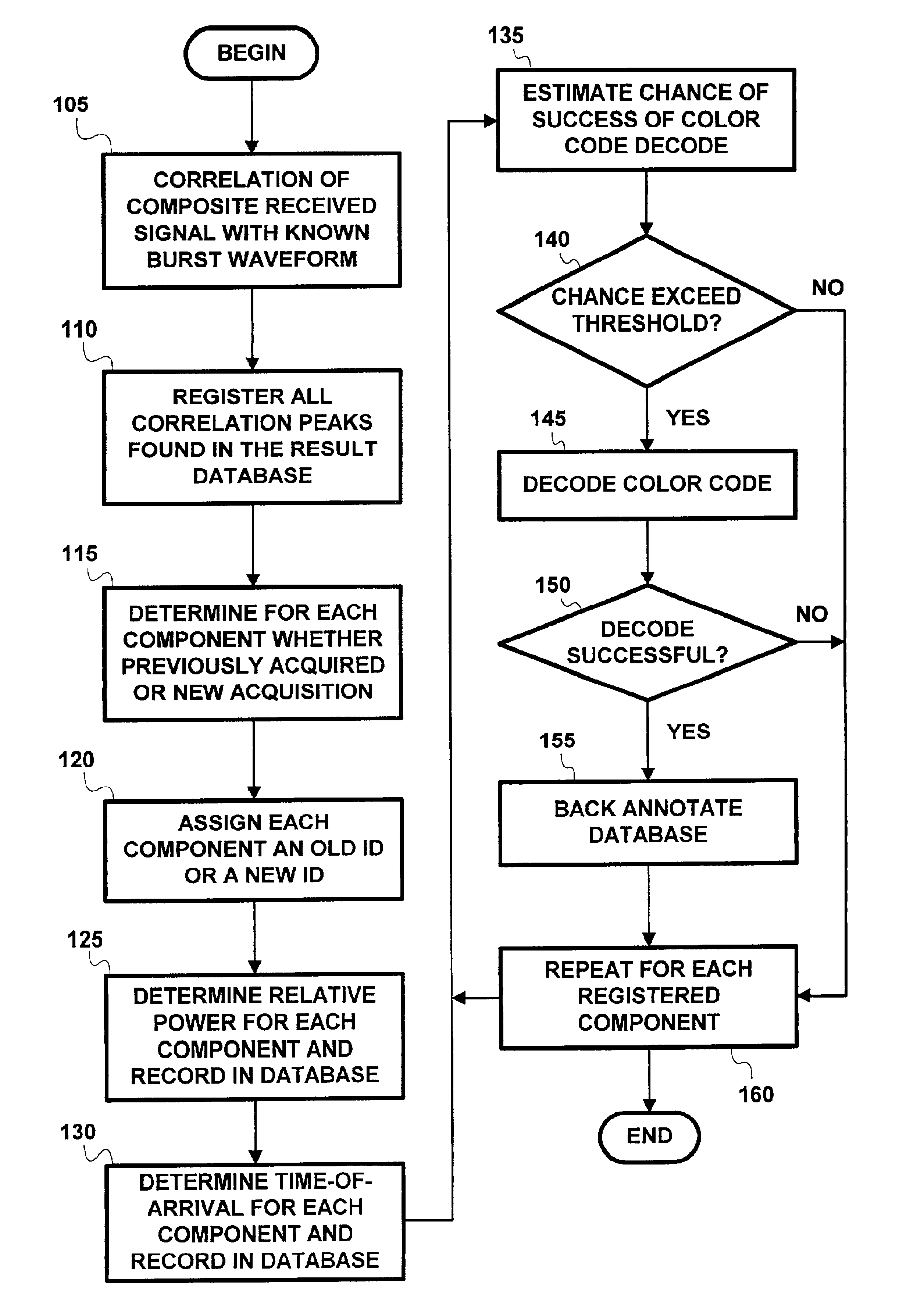
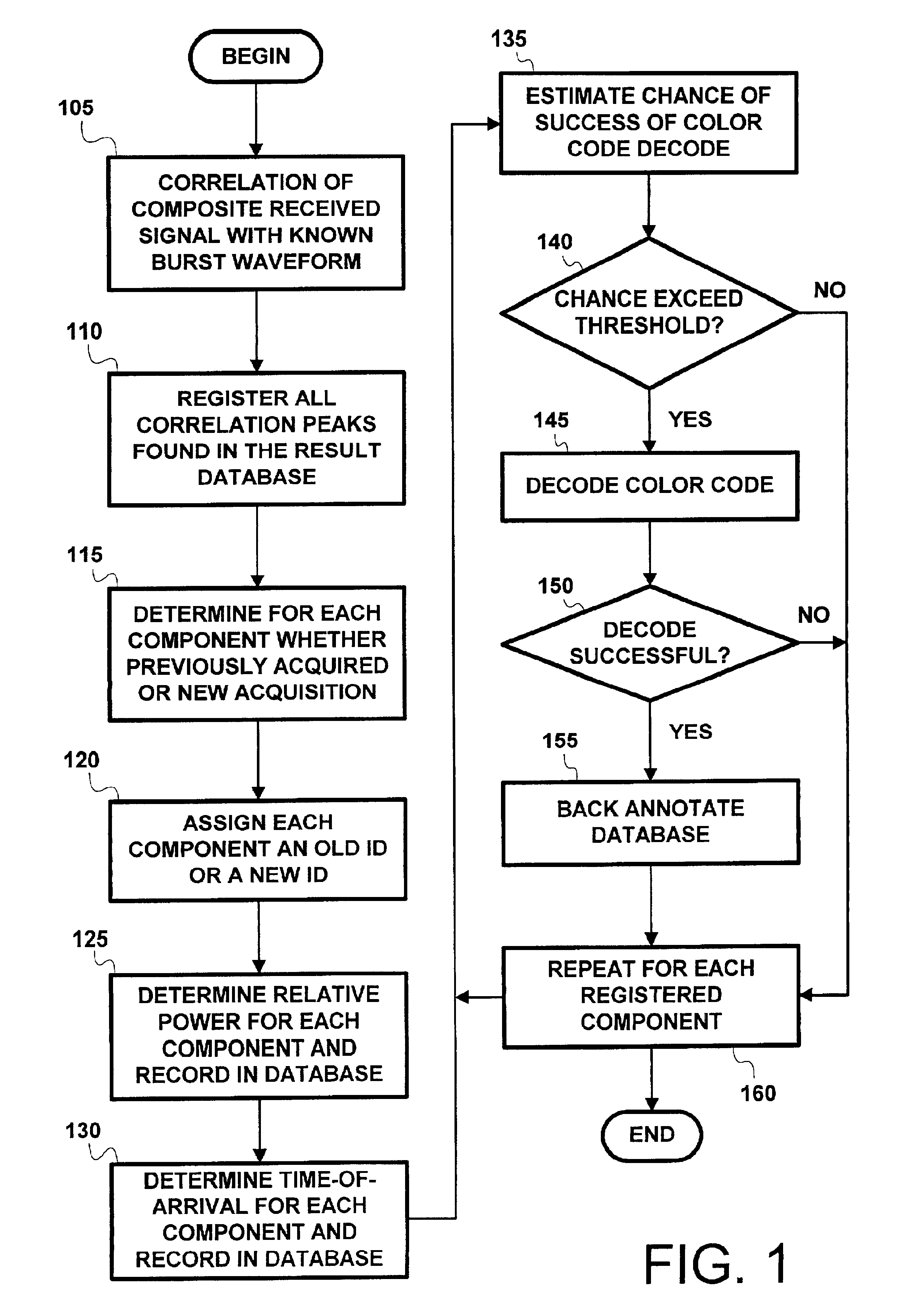
[0022]Co-channel interference in a wireless network is identified and quantified. Rather that using color code identification, a more reliable identification property of each co-channel component of the received composite signal is used, namely, the time of arrival of a known part of a signal. Detection and timing measurement is performed even in presence of stronger signals by focusing selectively on bursts having fixed contents (e.g., the FCCH burst used in GSM for frequency correction).

[0023]The repetitive measurements of the time-of-arrival of each of the interfering components of the signal during a drive test enables determination of the geographical location of the interfering co-channel base stations. An algorithm according to an embodiment of the present invention is described as follows.

[0024]Referring to FIG. 1, at each measurement point during the course of a drive test, correlate the received composite signal with the a prior known burst waveform 105, such as FCCH burst...


PUM


Abstract

Co-channel interference in a wireless network is identified and quantified. Rather that using color code identification, a more reliable identification property of each co-channel component of the received composite signal is used, namely, the time of arrival of a known part of a signal. Detection and timing measurement is performed even in presence of stronger signals by focusing selectively on bursts having fixed contents (e.g., the FCCH burst used in GSM for frequency correction). The repetitive measurements of the time-of-arrival of each of the interfering components of the signal during a drive test enables determination of the geographical location of the interfering co-channel base stations.

Description

CROSS REFERENCE TO RELATED APPLICATIONS[0001]The present application claims priority under 35 U.S.C. § 119(e) from provisional application No. 60 / 185,805, filed Feb. 29, 2000. The 60 / 185,805 provisional application is incorporated by reference herein, in its entirety, for all purposes.INTRODUCTION[0002]The present invention relates generally to the field of Time Division Multiple Access (TDMA) Cellular and Personal Communications System (PCS) networks. More particularly, the present invention relates to a method and apparatus for identification and measurement of co-channel interference in TDMA and / or PCS networks during drive testing.BACKGROUND OF THE INVENTION[0003]It is well known that one of the major limitations in cellular and PCS wireless telephone networks is the so-called co-channel interference. In the case of TDMA networks, such as GSM or NADC (otherwise known as “IS-136”), the co-channel interference is mainly caused by the fact that the spectrum allocated to the system ...

Claims


Application Information

Patent Timeline
IPC IPC(8): H04B7/08G01S19/03
CPCH04B7/086
Inventor KLINE, PAUL A.DICKEY, SERGEY L.
Owner PCTEL INC
Why Eureka
Try Eureka