Method for regulating the speed of a motor vehicle

a technology for controlling the speed of a motor vehicle and braking system, which is applied in the direction of process and machine control, braking system, instruments, etc., can solve the problem of insufficient deceleration of the vehicle, and achieve the effect of shortening the response time to the control command output to the braking system

Inactive Publication Date: 2005-08-23
ROBERT BOSCH GMBH
View PDF15 Cites 9 Cited by
  • Summary
  • Abstract
  • Description
  • Claims
  • Application Information

AI Technical Summary

Benefits of technology

[0006]It is an object of the present invention to provide a method for controlling speed such that the response time to a control command output to the braking system is shortened.
[0010]When, in the scope of the speed control, an intervention into the braking system of the vehicle may be necessary for whatever reason, this may announce itself in that the acceleration-demand signal becomes negative and approaches a value at which the deceleration attainable by the tractive resistance and the drag torque of the engine is no longer sufficient, and therefore it may be necessary to switch over to braking operation. By comparing the acceleration-demand signal to a suitable threshold value, it is therefore possible to recognize an imminent switchover to braking operation early and to preventatively preload the braking system, so that the braking system reacts more quickly in the event of actual activation. The shortening of the control delay thereby achieved makes it possible to better suppress unwanted control oscillations. In the case of a distance control, this means at the same time that falling below the setpoint distance is minimized, so that not only is comfort improved, but driving safety is increased as well.
[0011]Since according to an exemplary embodiment of the present invention, a drop of the acceleration-demand signal below a threshold value is utilized as a criterion for the output of the fill signal, the use of the method is independent of which control goals are being pursued with the speed control and which control algorithms are being used in detail. The method of an exemplary embodiment of the present invention is therefore applicable for a large range of different control concepts, and permits high flexibility with respect to later modifications or expansions of the control system.
[0012]The criterion for the actual activation of the braking system may possibly be defined in that the acceleration-demand signal falls below a triggering threshold which, on its part, may be varied dynamically as a function of the driving situation. The threshold value for the preloading of the braking system may then lie by a fixed differential amount above this triggering threshold. In practice, a lower limit is defined for the change rate of the acceleration-demand signal over time, this limit ensuring that the comfort and the feeling of safety for the vehicle passengers are not impaired by decelerations applied in a jerky manner. On the basis of this limit and on the basis of the filling time—determined by the design of the braking system—which may be necessary for preloading the braking system, it is possible to continually select the differential amount between the threshold value for the preloading of the braking system and the actual triggering threshold so that the preloading process is concluded before the brake is actually activated.

Problems solved by technology

However, when, for example, on downhill grades, or when, necessitated by distance, a stronger deceleration of the vehicle may be necessary, the drag torque of the engine is not adequate to bring about a sufficient deceleration of the vehicle, then an intervention in the braking system of the vehicle is carried out.
However, upon activation of the vehicle brake, a certain delay in response results due to the fact that the wheel brake cylinders and the remaining components of the hydraulic braking system have a certain dead volume which may need to first of all be filled with brake fluid before the brakes at the individual wheels of the vehicle actually become effective.

Method used


Image

  • Method for regulating the speed of a motor vehicle
  • Method for regulating the speed of a motor vehicle
  • Method for regulating the speed of a motor vehicle

Examples


Embodiment Construction

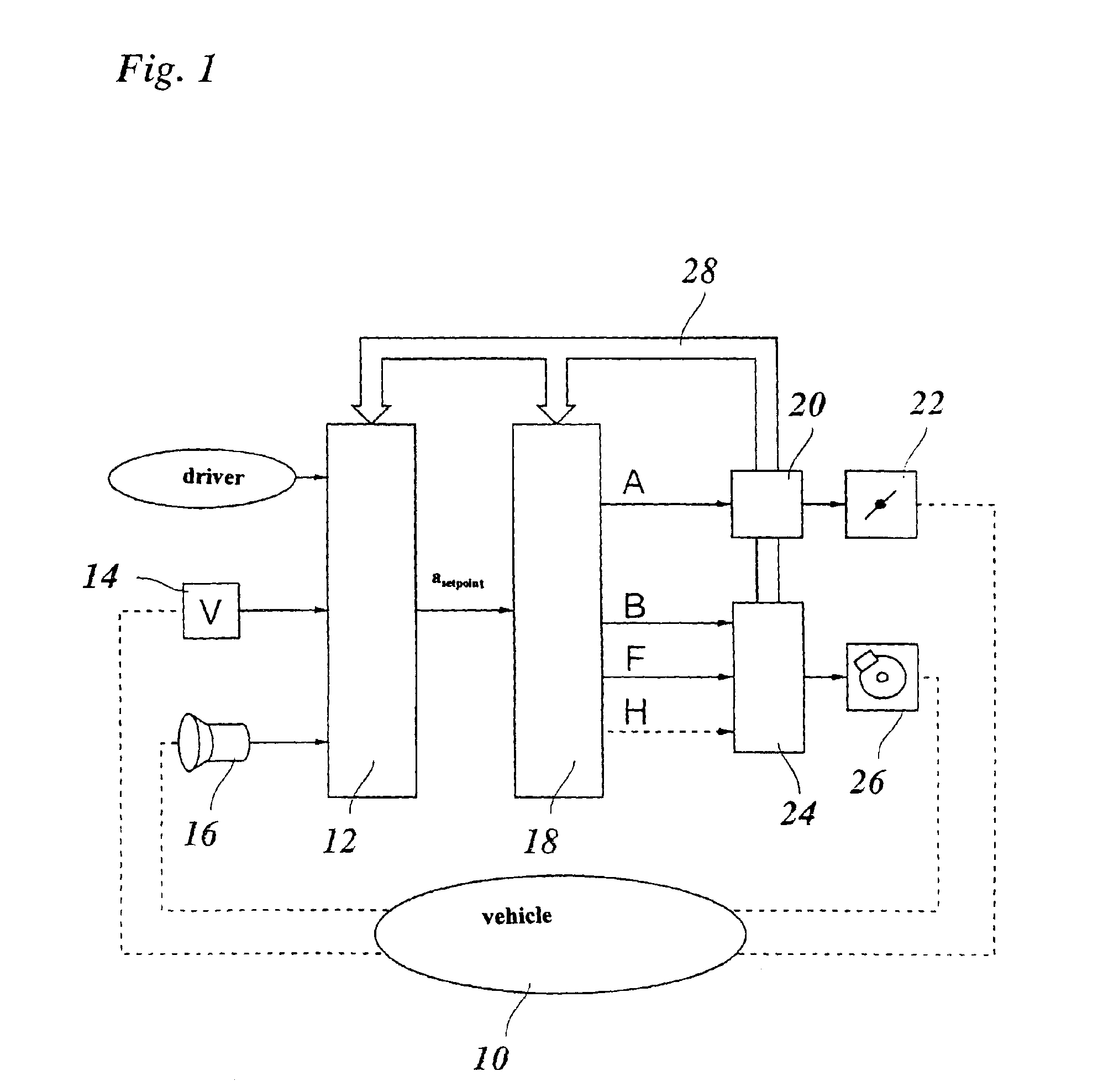
[0021]In FIG. 1, a motor vehicle is shown symbolically whose speed is controlled with the aid of an electronic controller 12. To that end, controller 12 receives a signal from a speed sensor 14 which indicates the actual speed of the vehicle. Furthermore, a distance sensor, in the example shown a radar sensor 16, is mounted in the front on the vehicle and reports distance data and relative-speed data of objects located in front of the vehicle to controller 12. Possibly, radar sensor 16 has a certain angular-resolution capability so that the azimuth angle of the located objects may also be detected and reported to controller 12. In this manner, the radar system and / or controller 12 are able to differentiate preceding vehicles in the vehicle's own lane from vehicles in other lanes, as well as from fixed targets at the edge of the roadway. When preceding vehicles are located in the vehicle's own lane, then the immediately preceding vehicle is selected as a target object, and the speed ...


PUM


Abstract

In a method for controlling the speed of a motor vehicle, an acceleration-demand signal is generated which represents a positive or negative setpoint acceleration of the vehicle, and either a control command is output to the engine or a control command is output to braking system of the vehicle as a function of this signal, wherein a signal for preloading the braking system is output when the acceleration-demand signal falls below a threshold value which lies above a value at which the braking system is activated.

Description

FIELD OF THE INVENTION[0001]The present invention relates to a method for controlling the speed of a motor vehicle, in which an acceleration-demand signal is generated which represents a positive or negative setpoint acceleration of the vehicle, and either a control command is output to the engine or a control command is output to the braking system of the vehicle as a function of this signal.BACKGROUND INFORMATION[0002]A method of this type is discussed in the publication “Adaptive Cruise Control System—Aspects and Development Trends” by Winner, Witte, Uhler and Lichtenberg, Robert Bosch GmbH, in the SAE Technical Paper Series 961010, International Congress & Exposition, Detroit, Feb. 26-29, 1996. The control system discussed in this publication, also known as an ACC system (adaptive cruise control), is based on a distance sensor, e.g. a radar sensor having multiple-target capability, which is mounted on the front side of the vehicle in order to measure distances to and relative sp...

Claims


Application Information

Patent Timeline
Patent Type & Authority Patents(United States)
IPC IPC(8): B60K31/00B60K31/04B60K31/02B60T7/22B60W10/04B60T7/12B60T8/00B60W30/16F02D29/02
CPCB60K31/0008B60K31/04B60T7/22B60W30/16B60T2201/12B60W2720/106
Inventor HELLMANN, MANFREDLAUXMANN, RALPHIRION, ALBRECHT
Owner ROBERT BOSCH GMBH
Why Eureka
Try Eureka