Channel letter lighting using light emitting diodes

Inactive Publication Date: 2005-08-23
THE SLOAN COMPANY INC DBA SLOANLED
View PDF20 Cites 199 Cited by
  • Summary
  • Abstract
  • Description
  • Claims
  • Application Information

AI Technical Summary

Benefits of technology

[0017]Lighting unit sand lighting systems according to the present invention are simple, cost effective and easy to use. The extrusion in the lighting units dissipate heat to that the LEDs can operate at a lower temperature. The lighting systems are flexible and c

Problems solved by technology

However, these light sources have a relatively short life (20,000 hours), are fragile, operate at high voltage (7,000 to 15,000 volts for neon) and can consume a relatively large amount of power.
Neon bulbs can also experience difficulty with cold starting, which can lead to the bulb's failure.
The Shwartz lighting arrangement is not compatible with channel letters because the channel letter housing does not have curved surfaces to reflect light forward.
Further the Shwartz arrangement can be prohibitively complex and costly for channel letters and the system provides no mechanism for dissipating heat in from the LEDs.
One disadvantage of the Hannah arrangement is that it is not flexible enough to be easily mounted to curved sectio

Method used


Image

  • Channel letter lighting using light emitting diodes
  • Channel letter lighting using light emitting diodes
  • Channel letter lighting using light emitting diodes

Examples


Embodiment Construction

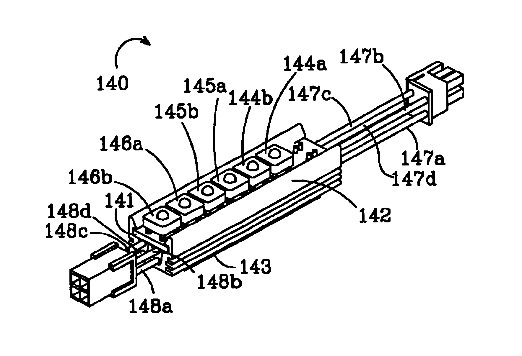
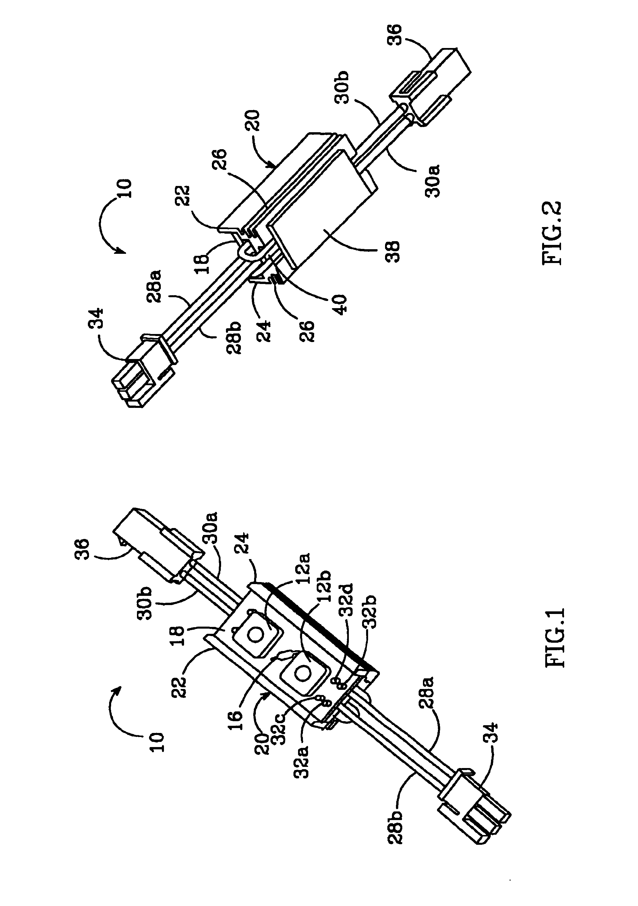
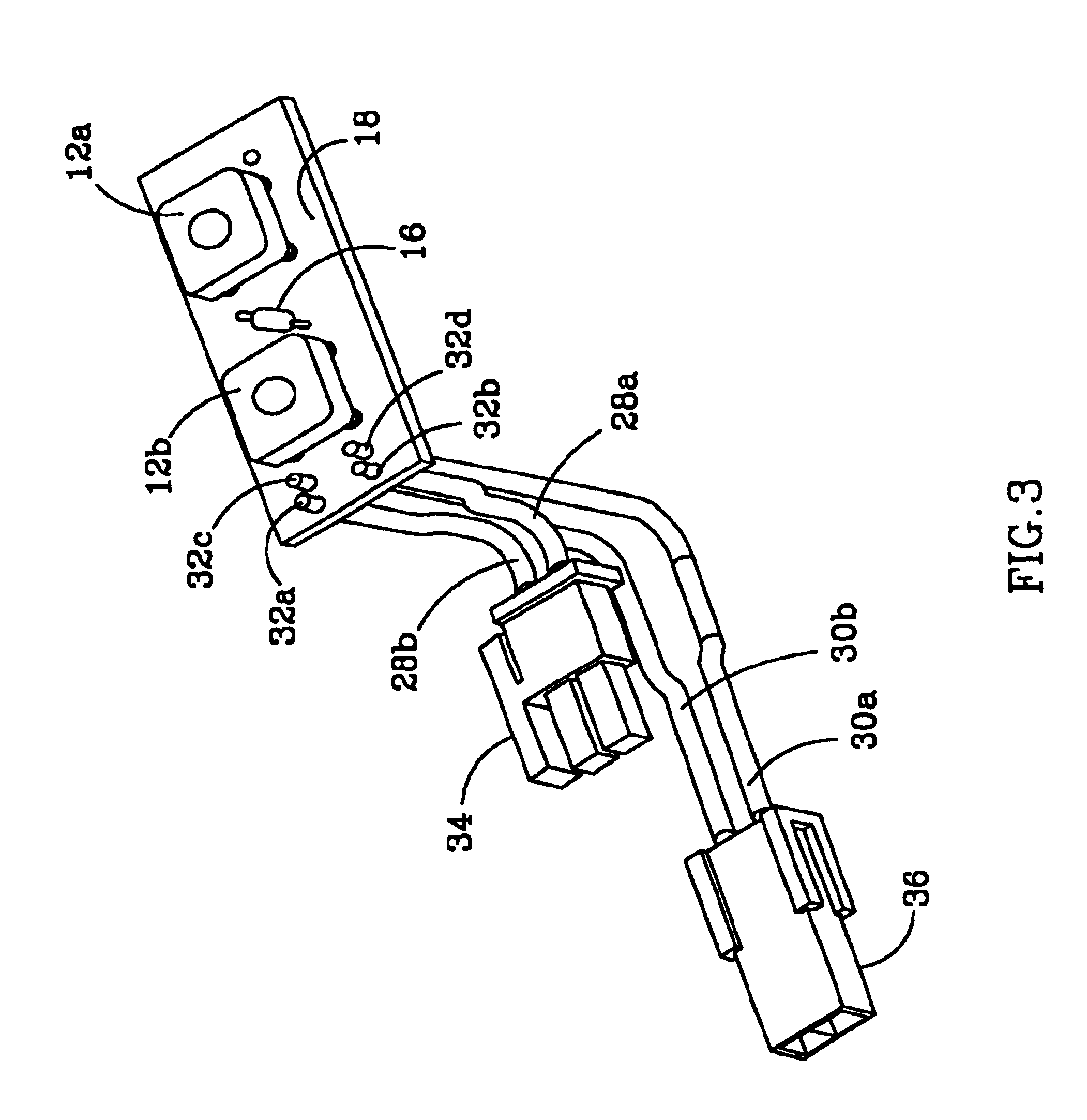
[0035]FIGS. 1 and 2 show one embodiment of the channel lighting unit 10 constructed in accordance with the present invention. It includes two LEDs 12a, 12b and a series resister 16 that are mounted to a PCB 18 by conventional methods. The PCB 18 could have a different number of LEDs and other passive components and the LEDs can emit the same or different colors of light. In one embodiment of the unit 10 the LEDs 12a, 12b emit red light. The LEDs 12a and 12b provide high luminous flux and have a wide viewing angle.

[0036]The PCB 18 has conventional interconnecting conductive traces (not shown) to provide the interconnections between the LEDs 12a, 12b and the resister 16. The PCB 18 is mounted within an extrusion 20, which can be made of many different thermally conductive materials such as aluminum. The PCB 18 is mounted on the extrusion 20 closely between two vertical strips 22, 24 that run along the longitudinal edges of the PCB 18. The strips 22, 24, provide some protection for the...


PUM


Abstract

A channel letter lighting unit according to the present invention comprises a printed circuit board (PCB) having a plurality of linearly mounted light emitting elements. Input wires transmit a power signal to the PCB to illuminate the plurality of light emitting elements, and output wires transmit the power signal from the PCB. The PCB is mounted in the extrusion and the light emitting elements transmit light away from the extrusion. The extrusion promotes the dissipation of heat from the light emitting elements. A mounting mechanism is included for mounting the extrusion within a housing. A further embodiment according to the invention comprises a plurality of channel lighting units electrically connected to one another so that a power signal applied to the lighting system is transmitted to each of the plurality of lighting units. A still further embodiment according to the invention comprises an illuminated channel letter system having a housing in the shape of a letter. A translucent lens is included over the housing to transmit light from within the housing. A plurality of channel lighting units are mounted within the housing and coupled to one another in a daisy chain. A power signal applied to the first of the plurality of lighting units in the daisy chain is transmitted to the remaining of the plurality of lighting units.

Description

[0001]This application claims the benefit of provisional application Ser. No. 60 / 326,276 to Sloan et al., which was filed on Oct. 1, 2001.BACKGROUND OF THE INVENTION[0002]1. Field of the Invention[0003]This invention relates to lighting units using light emitting diodes (LEDs) and more particularly to LED based lighting units for illuminating channel letters.[0004]2. Description of the Related Art[0005]Recent developments in LEDs have resulted in devices that are brighter, more efficient and more reliable. LEDs are rugged, consume less power, have a relatively long life (up to 100,000 hours), operate at low voltage (7V), and are 30 to 70% more energy efficient than conventional lights, such as neon or fluorescent bulbs.[0006]Channel letters are commonly found on the outside of buildings and are often used to advertise the name of the business. They are typically constructed of an aluminum or plastic housing that is in the shape of a letter and is approximately 5″ deep. The housing h...

Claims


Application Information

Patent Timeline
IPC IPC(8): G09F13/22F21V29/00F21S4/00
CPCF21V21/0808F21V29/76G09F13/22G09F13/0404F21S4/003F21V29/004F21Y2101/02Y10S362/80Y10S362/812F21Y2103/003F21V29/74F21S4/20F21Y2103/10F21Y2115/10
Inventor SLOAN, THOMAS C.QUAAL, BRUCE
Owner THE SLOAN COMPANY INC DBA SLOANLED
Why Eureka
Try Eureka