Controlling the characteristics of implanter ion-beams

a technology of implanter ion beams and characteristics, applied in the field of control of implanter ion beam characteristics, can solve the problems of active control, generating dipole field contributions, and inability to achieve full-length ribbon extraction, etc., and achieve the effect of eliminating magnetic short circuits

Inactive Publication Date: 2005-08-23
PURSER KENNETH H +2
View PDF4 Cites 46 Cited by
  • Summary
  • Abstract
  • Description
  • Claims
  • Application Information

AI Technical Summary

Benefits of technology

[0016]In an embodiment of the present invention, a rectangular steel window frame construction provides the magnetic supporting structure needed for producing the wanted deflection fields. A feature of the present embodiment is that the windings along the long-axis bars consist of a large number of independently excited short sections. This concept allows high-order multipoles to be generated without dedicated windings and the central point of any multipole contribution can be translated along the transverse x-axis. Additional coils around the end bars are essential for eliminating magnetic short circuits when multipole components are being generated. However, these end-bar coils can also be excited independently in a manner that allows the production of a pure dipole field between the long-axis bars at right angles to the long dimension of the rectangle. Finally, when the coils on the end bars are switched off, dipole fields can be generated along the long axis of the window frame.
[0017]In another embodiment of the present invention, local variations in ion density or the shape of the ribbon beam at the exit from the source are corrected by locally modifying the deflecting fields. These corrections can be made under computer control and on a time scale that is only limited by the decay rate of eddy currents in the steel. The input beam parameters needed for control involves position-sensitive faraday cups for measuring the intensity and angle distribution of ions within said ribbon beam allowing discrepancies from the wanted distribution to be corrected by modifying the deflection fields.

Problems solved by technology

While in principle it is feasible to generate a wanted shape of ribbon beam directly from an ion source, in a practical situation full-length ribbon extraction may not be feasible.
They suffer disadvantages when active control of the deflecting fields is needed to correct beam parameters.
First, neither design generates a dipole field contribution where the B-field is along the long axis of the rectangle.
Secondly, the symmetry point (x=0) is usually established from the geometry of the coils and of the steel yokes so there is no easy way to introduce steering about the y-axis by moving the center of the lens-field distribution.

Method used


Image

  • Controlling the characteristics of implanter ion-beams
  • Controlling the characteristics of implanter ion-beams
  • Controlling the characteristics of implanter ion-beams

Examples


Embodiment Construction

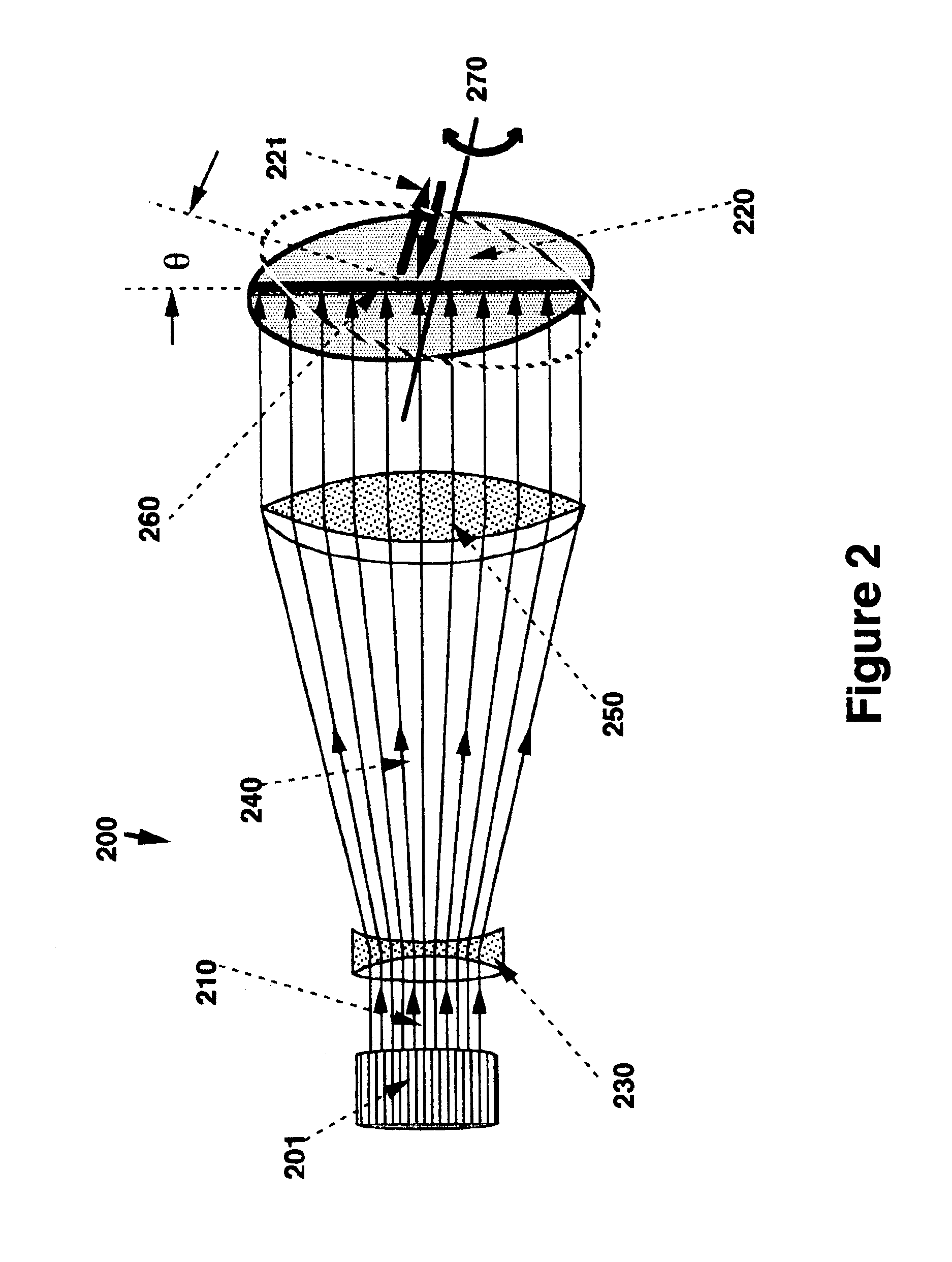
[0042]The unique properties of the system according to the present invention will be better elucidated by reference to a practical example. In this example, a pair of quadrupole lenses are used to expand an initially parallel set of beamlets to a broader set of parallel beamlet trajectories.

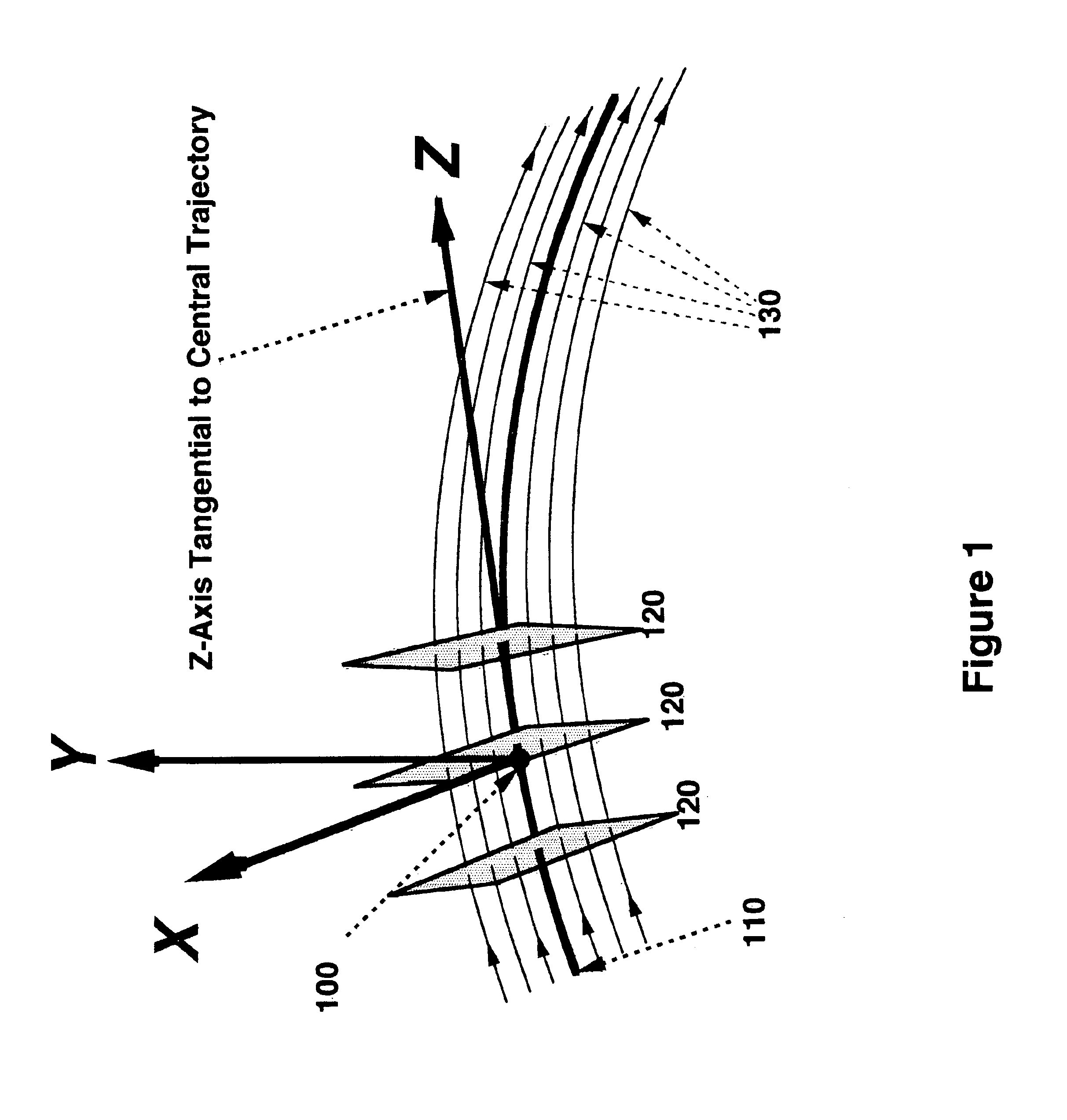
[0043]FIG. 1 illustrates the beam coordinate system used in the following discussions. Three representative sections, 120, across a ribbon beam are shown. The X-axis is always aligned with the surfaces, 120, at right angles to the beamlets, 130, comprising the ribbon beam and along the surface's long axis. The Z-axis, 110, is tangential to the central trajectory, of the ribbon beam and remains coincident with the central trajectory throughout the length of the ion optical transport system, causing it to change direction as the central trajectory, 110, changes direction. At each point along the beam path the Cartesian Y-axis lies also in the surface, 120, and along the ribbon beam's cross-sectiona...


PUM


Abstract

A method and apparatus satisfying growing demands for improving the precision of angle of incidence of implanting ions that impact a semiconductor wafer and the precision of ribbon ion beams for uniform doping of wafers as they pass under an ion beam. The method and apparatus are directed to the design and combination together of novel magnetic ion-optical transport elements for implantation purposes. The design of the optical elements makes possible: (1) Broad-range adjustment of the width of a ribbon beam at the work piece; (2) Correction of inaccuracies in the intensity distribution across the width of a ribbon beam; (3) Independent steering about both X and Y axes; (4) Angle of incidence correction at the work piece; and (5) Approximate compensation for the beam expansion effects arising from space charge. In a practical situation, combinations of the elements allow ribbon beam expansion between source and work piece to 350 millimeter, with good uniformity and angular accuracy. Also, the method and apparatus may be used for introducing quadrupole fields along a beam line.

Description

CROSS REFERENCE AND RELATED APPLICATIONS[0001]This Application claims priority to U.S. provisional patent application Ser. No. 60 / 396,322 filed Jul. 17, 2002 entitled “Controlling the Characteristics of Implanter Ion Beams” the disclosure of which is incorporated herein by reference in its entirety.FIELD OF INVENTION[0002]The disclosed methods and apparatus relate generally to the construction and use of magnetic focusing and correction elements for modifying the intensity distribution of ions within ribbon beams and more particularly to precision correction of the angle of incidence of ions used for implanting and doping in semiconductor devices.BACKGROUND TO THE INVENTION[0003]The process of ion implantation is useful in semiconductor manufacturing as it makes possible the modification of the electrical properties of well-defined regions of a silicon wafer by introducing selected impurity atoms, one by one, at a velocity such that they penetrate the surface layers and come to rest...

Claims


Application Information

Patent Timeline
Patent Type & Authority Patents(United States)
IPC IPC(8): H01J37/08H01L21/02H01L21/425H01J37/141H01J37/14H01J37/147H01J37/315H01J37/317
CPCH01J37/14H01J37/141H01J37/147H01J37/1472H01J37/153H01J37/315H01J37/3171H01J2237/141H01J2237/1534H01J2237/31703H01J37/317
Inventor PURSER, KENNETH H.ENGE, HARALD A.TURNER, NORMAN L.
Owner PURSER KENNETH H
Why Eureka
Try Eureka