Acoustic wave sensor with EMAT drive

a technology drive, which is applied in the field of acoustic wave sensor having an electromagnetic acoustic transducer, can solve the problems of metals and the like not being used, the type of switch is expensive, and the piezoelectric element is relatively unprotected

Inactive Publication Date: 2005-08-23
TEXZEC
View PDF14 Cites 17 Cited by
  • Summary
  • Abstract
  • Description
  • Claims
  • Application Information

AI Technical Summary

Problems solved by technology

Further, the enclosure through which touch is sensed cannot be made of an electrically conducting material, so that metals and the like cannot be used.
This type of switch is expensive compared to a standard membrane switch and shares the disadvantages of membrane switches in that holes in the housing or enclosure are required to accommodate the switch.
Further, the metal overlay is necessarily thin, so that the piezoelectric element is relatively unprotected against blows to the overlay.
This type of switch is relatively expensive and again requires openings in the housing or enclosure in which the switch is to be mounted.
As such, the ratio of the stored energy to lost or dissipated energy over a complete cycle, referred to as the Q of the switch, is inherently low and an extremely complex touch detection circuit is required to discriminate between a touch and the absence of a touch.
Moreover, the use of compressional waves in this switch is undesirable due to their sensitivity to liquids and other contaminants which can render the switch inoperable.
These systems are undesirable, however, because surface acoustic waves are sensitive to liquids, sealing compounds and other contaminants that can render the panel inoperable and difficult to seal effectively.
Although this touch position sensor is insensitive to liquids and contaminants, touch position sensors that use reflective gratings or arrays and the associated touch detection circuitry are, in general, too expensive to use for an individual switch or for a small number of switches on a panel.
Although an Electromagnetic Acoustic Transducer (EMAT) is known for generating acoustic waves, this type of transducer has not been used in known acoustic wave switches or touch panels.
That is because EMATs are very inefficient converters of electrical energy to acoustic wave energy.
As such, special amplifiers and electromagnetic shielding techniques are required as well as complicated signal processing circuits.
Another factor that limits the use of EMATs is that they require an electrically conducting substrate in which to induce the acoustic wave.

Method used


Image

  • Acoustic wave sensor with EMAT drive
  • Acoustic wave sensor with EMAT drive
  • Acoustic wave sensor with EMAT drive

Examples


first embodiment

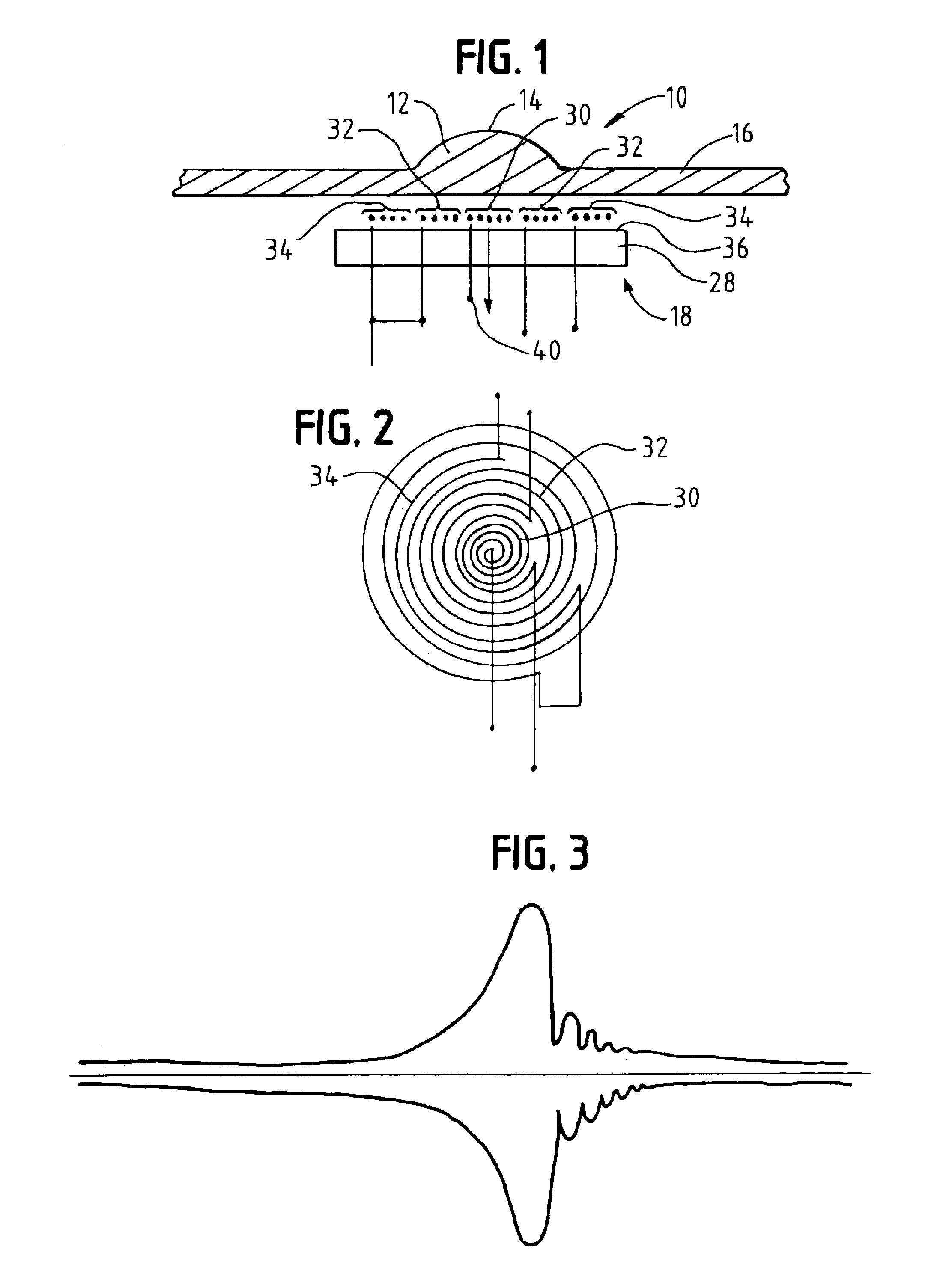
[0027]As shown in the present invention, the EMAT 18 includes a magnet 28 and concentric, spiral primary coil 30, pickup coil 32 and noise canceling coil 34 mounted on a surface 36 of the magnet 28 spaced from the substrate 16. In this embodiment, the primary coil 30 is the inner-most coil having a drive signal applied to a lead 40 thereof. The pickup coil 32 is a spiral coil adjacent to and concentric with the primary coil 30. In this embodiment, both the primary and pickup coils 30 and 32 are directly beneath the acoustic wave cavity 12. The noise canceling coil 34 is adjacent to the pickup coil 32 and concentric with the primary and pickup coils 30 and 32; however, the acoustic wave cavity 12 does not overlie the noise canceling coil 34. In this embodiment, the outer end of the pickup coil is connected to the outer end of the noise canceling coil and the output signal of the acoustic wave sensor is the voltage between the inner or starting end of the pickup coil 32 and the starti...

second embodiment

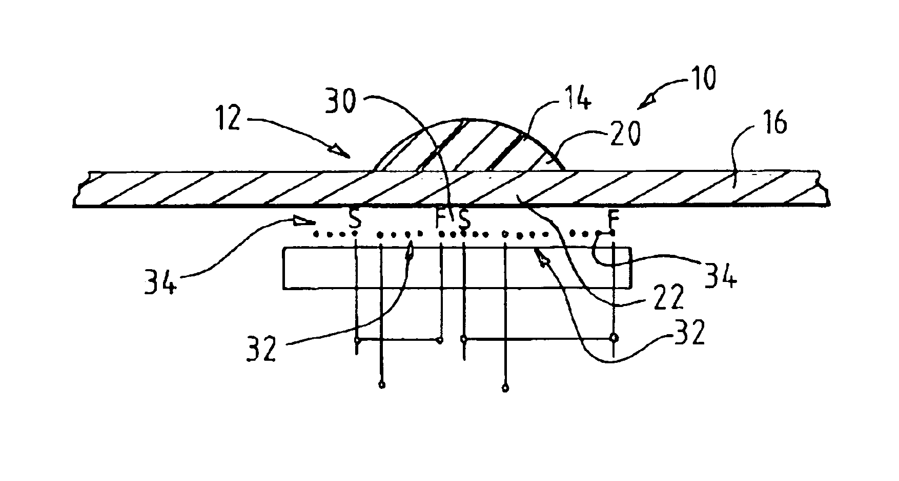
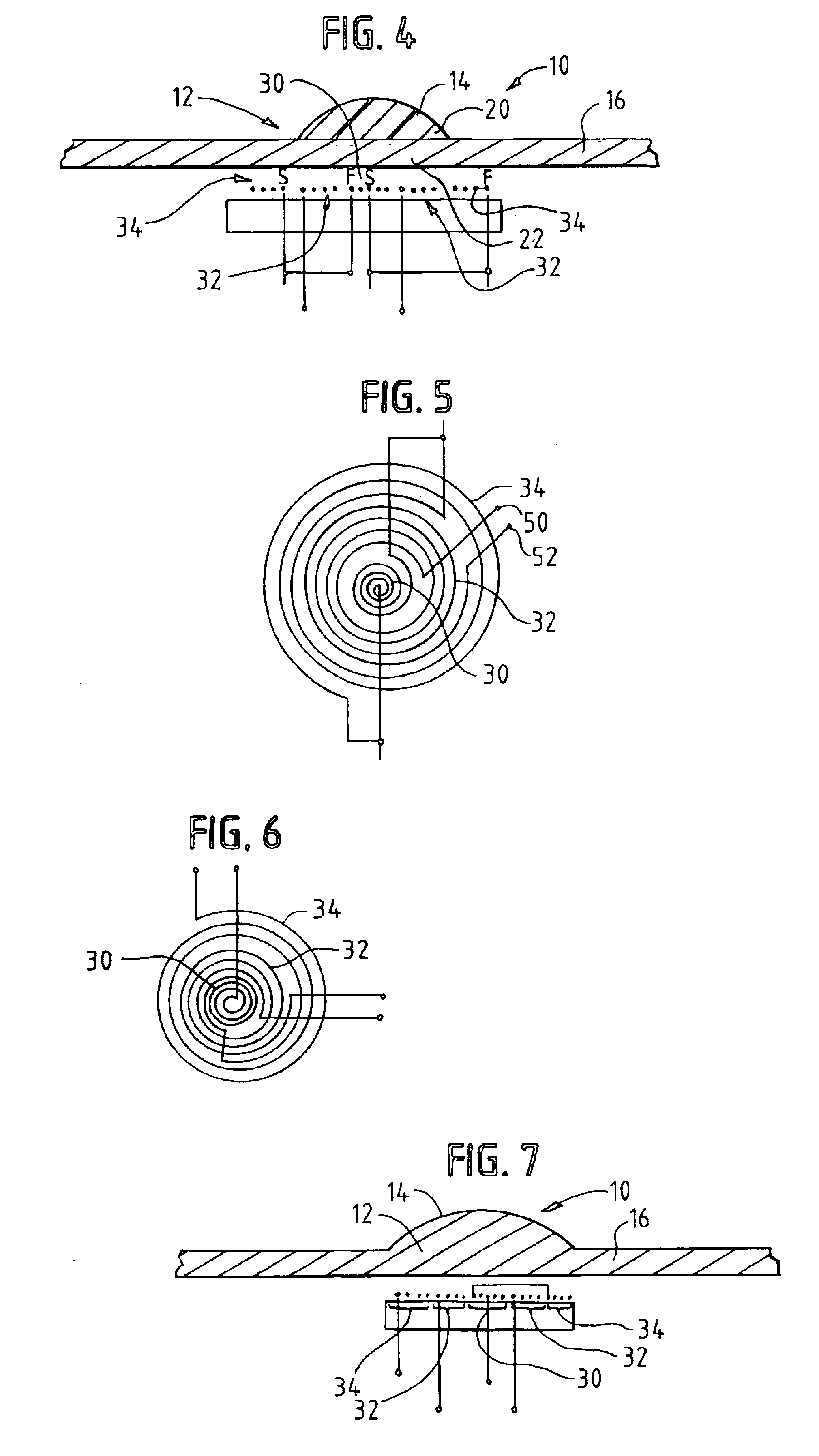
[0028]In the present invention, as illustrated in FIGS. 4 and 5, the noise canceling coil 34 is driven 180° out of phase with the primary coil wherein the concentric primary and pickup coils 30 and 32 are directly underneath the acoustic wave cavity 12 whereas the acoustic wave cavity 12 does not overlie the noise canceling coil 34. In this embodiment, the start of the primary coil 30 is connected to the outer or finishing end of the noise canceling coil 34 and the finishing or outer end of the primary coil 30 is connected to the start or inner end of the noise canceling coil 34. The output of the acoustic wave sensor is obtained between the two ends 50 and 52 of the pickup coil, the output representing the acoustic wave energy in the cavity 12 with the spurious current induced by the primary having been cancelled.

third embodiment

[0029]In the present invention, as shown in FIGS. 6 and 7, one coil forms both the inner primary coil portion 30 and the outer noise canceling portion 34 of the EMAT wherein the pickup coil is disposed in a space between the primary portion 30 and the noise canceling portion 34 of the first coil. In this embodiment, the concentric coils are all contained underneath the acoustic wave cavity so as to provide the most compact EMAT arrangement. More particularly, the primary coil portion 30 forms an inner coil that is connected to the outer most coil portion forming the noise canceling coil portion 34. The pickup coil 32 is concentric with the primary and noise canceling portions of the first coil but is disposed in a space therebetween. The acoustic wave cavity 12 overlies all three coil portions 30, 32 and 34.

[0030]FIG. 8 illustrates one magnet configuration for the EMAT 28. In this configuration, a magnet 52 with its north pole adjacent the substrate 16 is positioned next to a magnet...


PUM


Abstract

An acoustic wave sensor includes an electromagnetic acoustic transducer to generate a resonant acoustic wave substantially trapped in an acoustic wave cavity. The acoustic wave cavity is defined by a radially symmetric raised surface. The electromagnetic acoustic transducer includes a spiral primary coil to generate the acoustic wave in the acoustic wave cavity and a concentric spiral pickup coil to pick up an electrical signal representing the acoustic wave in the cavity. A noise canceling coil portion is used to cancel spurious noise induced by the primary coil from the pickup coil to provide an output signal representing the acoustic wave energy in the cavity 12.

Description

CROSS-REFERENCE TO RELATED APPLICATIONS[0001]This application is related to U.S. patent applications Ser. No. 09 / 998,355 filed Nov. 20, 2001 and Ser. No. 09 / 998,220, filed Nov. 20, 2001.STATEMENT REGARDING FEDERALLY SPONSORED RESEARCH OR DEVELOPMENT[0002]N / AFIELD OF THE INVENTION[0003]The present invention relates to an acoustic wave sensor and more particularly to an acoustic wave sensor having an electromagnetic acoustic transducer for generating a resonant acoustic wave in an acoustic wave cavity formed in the body of the sensor.BACKGROUND OF THE INVENTION[0004]There is a substantial need for finger touch actuated switches that are rugged and explosion proof, operate in the presence of liquids, have low power consumption, withstand aggressive sterilization procedures and are inexpensive. Known switches that attempt to meet these needs but fail include the following. A Qprox switch made by Quantum Research Group senses the presence of touch through a charge transfer effect. This s...

Claims


Application Information

Patent Timeline
Patent Type & Authority Patents(United States)
IPC IPC(8): H03K17/94H03K17/96
CPCH03K17/96H03K2217/96011
Inventor KNOWLES, TERENCE J.
Owner TEXZEC
Why Eureka
Try Eureka