Laser microscope

a laser microscope and microscope technology, applied in the field of laser microscopes, can solve the problems of difficult removal of the possibility of optical axes misalignment, misalignment, and misalignment, and achieve the effect of suppressing the generation of misalignmen

Inactive Publication Date: 2005-08-23
OLYMPUS OPTICAL CO LTD +1
View PDF10 Cites 14 Cited by
  • Summary
  • Abstract
  • Description
  • Claims
  • Application Information

AI Technical Summary

Benefits of technology

[0020]The present invention provides a laser microscope which suppresses generation of misalignment, ...

Problems solved by technology

However, basically, it is difficult to remove the possibility that misalignment of the optical axes will occur.
For example, even if an ideal adjustment is carried out, there is the possibility that misalignment will occur due to effects such as changes in the environmental temperature, vibration, or the like.
Thus, even if the exiting orientations of the pump beam ω11 and the Stokes beam ω22 coincide, there is the possibility that misalignment will occur.
Accordingly, due to misalignment occurring, the strength of the ...

Method used


Image

  • Laser microscope
  • Laser microscope
  • Laser microscope

Examples


first embodiment

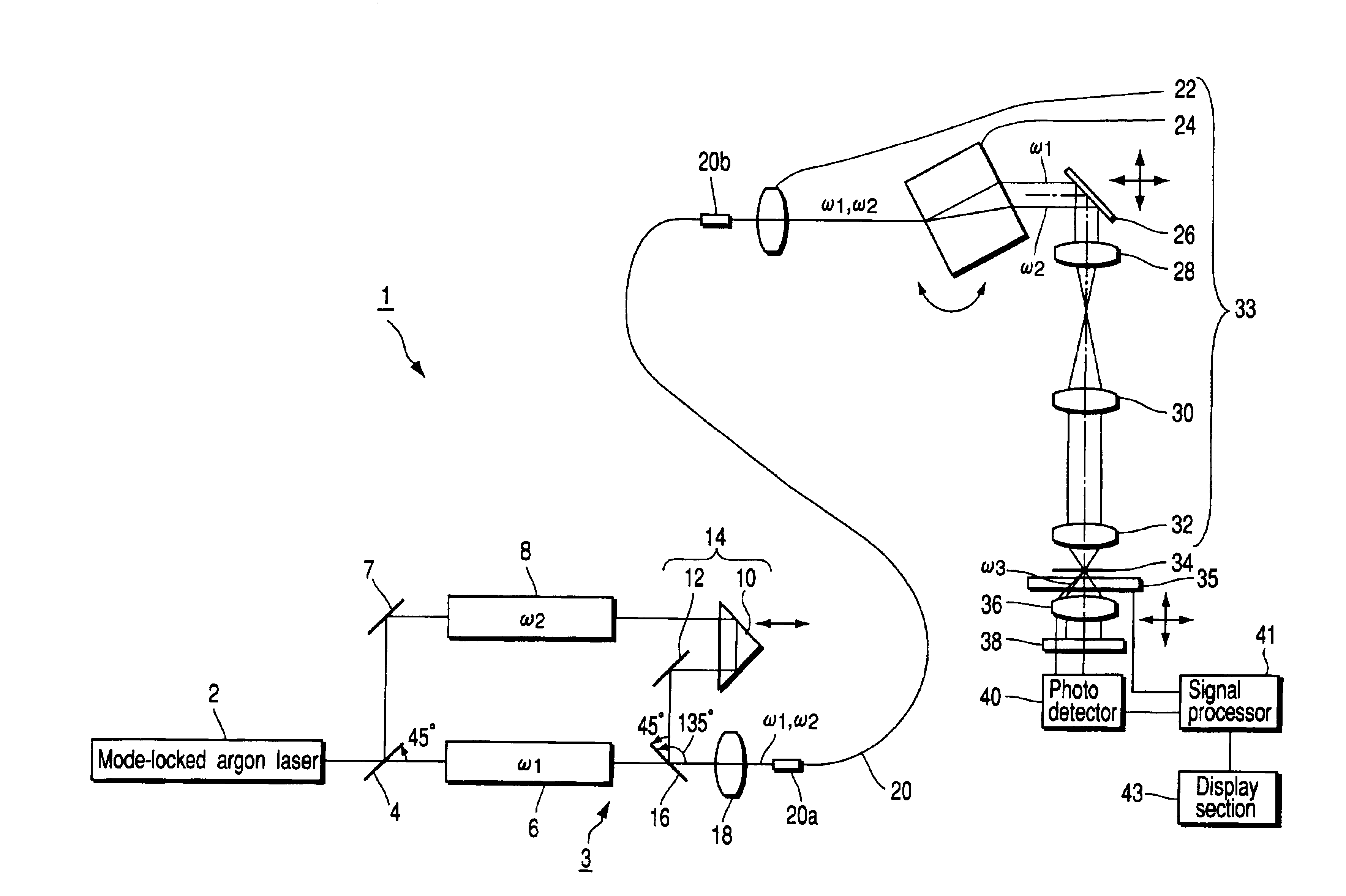
[0037]First, the invention will be described by using FIGS. 1 through 3.

[0038]As shown in FIG. 1, a laser microscope 1 is provided with, as a laser light emitting system 3, a mode-locked argon laser (a laser light source) 2 which emits a laser beam in a predetermined direction from a light-emitting opening (not shown). A beam splitter 4 is disposed in front of the laser 2. The beam splitter 4 divides the incident laser beam into a transmitted beam and a reflected beam to be reflected in a direction perpendicular to the transmitted beam. A first dye laser 6, which emits a pump beam ω1 (wavelength of 570 nm), is disposed on an optical path of the transmitted beam.

[0039]On the other hand, a reflecting mirror 7 and a second dye laser 8 which emits a Stokes beam ω2 (whose wavelength is variable from 620 nm to 680 nm) are disposed on the optical path of the reflected beam.

[0040]Note that the first and second dye lasers 6, 8 are respectively pulse oscillated at the same repeating frequenci...

second embodiment

[0082]Here, in the second embodiment, the dispersion compensating optical system 58 which can provide a large negative dispersion is disposed on each optical path of the pump beam ω1 and the Stokes beam ω2, such that the beams ω1, ω2 emitted from the single mode fiber 20 are emitted at a pulse width of a picosecond level.

[0083]Further, as the amount of negative dispersion of the dispersion compensating optical system 58, a value offsetting the sum of the amounts of dispersion of the optical elements disposed on the respective optical paths is preferably selected.

[0084]However, in this embodiment, the total of the amounts of the dispersion from the condenser lens 18 to the collimator lens 22 and from the plane parallel body 24 to the objective lens 32 does not reach a value offsetting the dispersion of the dispersion compensating optical system 58. Therefore, the high-dispersion glass 60, which can provide a positive dispersion, such as, for example, SF10, is disposed on the optical ...


PUM


Abstract

A laser microscope includes a laser light emitting system which emits a pump beam and a Stokes beam having different frequencies, and a common optical fiber having one end and the other end. The pump beam and the Stokes beam emitted from the laser light emitting system are incident on the one end thereof and emitted from the other end thereof. A beam irradiating mechanism condenses and irradiates the pump beam and the Stokes beam emitted from the other end of the optical fiber, onto a sample via the objective lens, thereby making an anti-Stokes beam be emitted from the sample. A photo detector detects the anti-Stokes beam emitted from the sample. A beam selecting mechanism allows only the anti-Stokes beam of the pump beam, the Stokes beam and the anti-Stokes beam to be received on the photo detector.

Description

CROSS-REFERENCE TO RELATED APPLICATIONS[0001]This application is based upon and claims the benefit of priority from the prior Japanese Patent Application No. 2001-202584, filed Jul. 3, 2001, the entire contents of which are incorporated herein by reference.BACKGROUND OF THE INVENTION[0002]1. Field of the Invention[0003]The present invention relates to a laser microscope irradiating a pump beam and a Stokes beam having different frequencies onto a sample, and detecting an anti-Stokes beam emitted from the sample, thereby obtaining an image.[0004]2. Description of the Related Art[0005]To date, in fields of research in medical science or biology, the study of cell functions has been actively carried out. In recent years, not only cell functions are studied, but also, the need to directly study the relationship between the function which is the subject and the protein molecular structure has increased.[0006]A method of directly observing Raman scattering light called a molecular fingerp...

Claims


Application Information

Patent Timeline
IPC IPC(8): G02B21/00G01N21/65G02B21/06
CPCG02B21/002
Inventor SHIMADA, YOSHIHIRO
Owner OLYMPUS OPTICAL CO LTD
Why Eureka
Try Eureka