
Chromatic dispersion compensation device having an array of micromirrors

a compensation device and chromatic dispersion technology, applied in multiplex communication, instruments, optical elements, etc., can solve the problems of reducing the sensitivity of the receiver to distinguish bits, limiting chromatic dispersion is a limiting factor to the speed of data transmission, etc., to achieve the effect of reconfigurability

Inactive Publication Date: 2005-08-23
II VI DELAWARE INC
View PDF43 Cites 32 Cited by
  • Summary
  • Abstract
  • Description
  • Claims
  • Application Information

AI Technical Summary

Benefits of technology

[0012]An object of the present invention is to provide a chromatic dispersion compensation device having a spatial light modulator that includes a micromirror device having an array of micromirrors, wherein the dispersion compensation device selectively delays a plurality of spectral bands of each respective wavelength band of light (i.e., optical channels) of an optical WDM input signal, which advantageously permits the device to be reconfigurable by changing a switching algorithm that drives the micromirrors, without having to change the hardware configuration.

Problems solved by technology

At these higher bit rates, the broadening of the light pulses (or bits) may result in the overlapping of adjacent bits, and thus reduces the sensitivity of the receiver to distinguish the bits.
Consequently, chromatic dispersion is a limiting factor to the faster transmission of data.
Unfortunately, a chirped fiber Bragg grating has a very narrow bandwidth for reflecting pulses, and therefore cannot provide a wavelength band sufficient to compensate for light including many wavelengths, such as a wavelength division multiplexed light.
A number of chirped fiber Bragg gratings may be cascaded for wavelength multiplexed signals, but this results in an expensive system.
They are also cumbersome and their properties can only be changed in discrete steps since change is accomplished by switching lengths of fiber in and out of the compensator.

Method used


Image

  • Chromatic dispersion compensation device having an array of micromirrors
  • Chromatic dispersion compensation device having an array of micromirrors
  • Chromatic dispersion compensation device having an array of micromirrors

Examples


Embodiment Construction

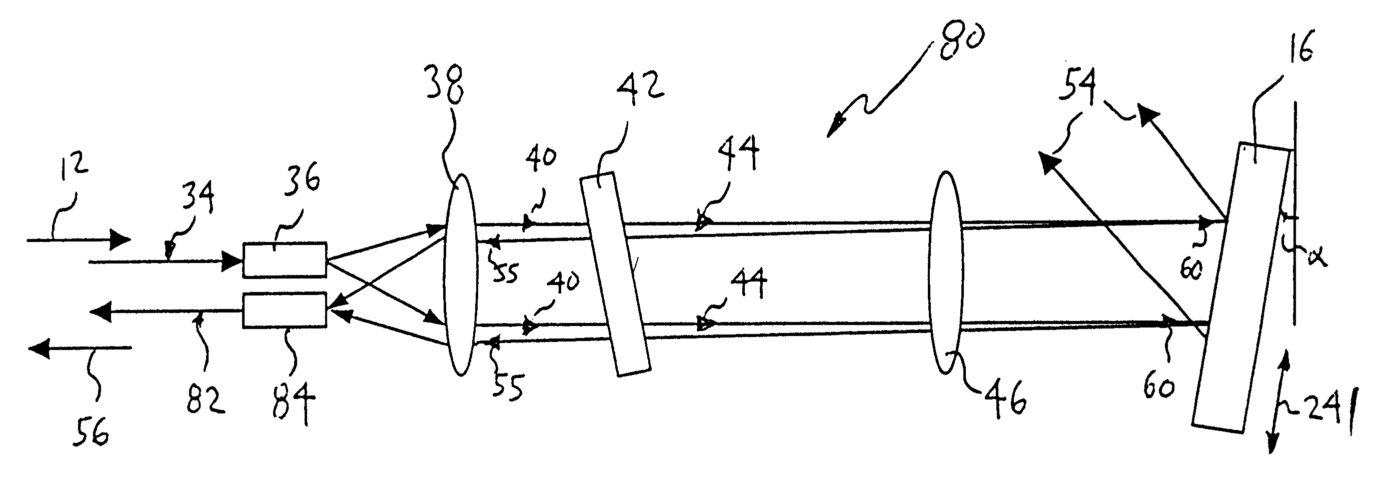
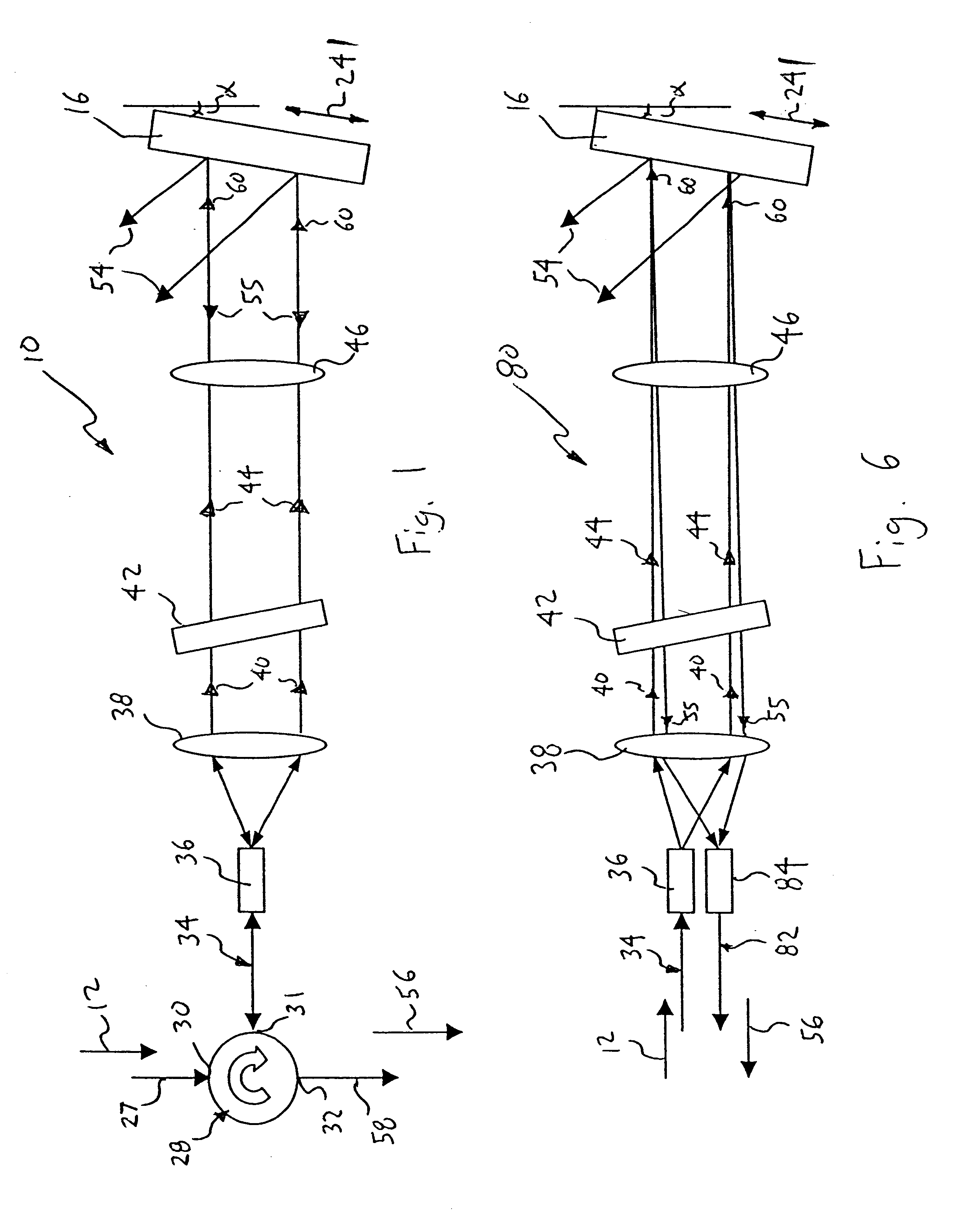
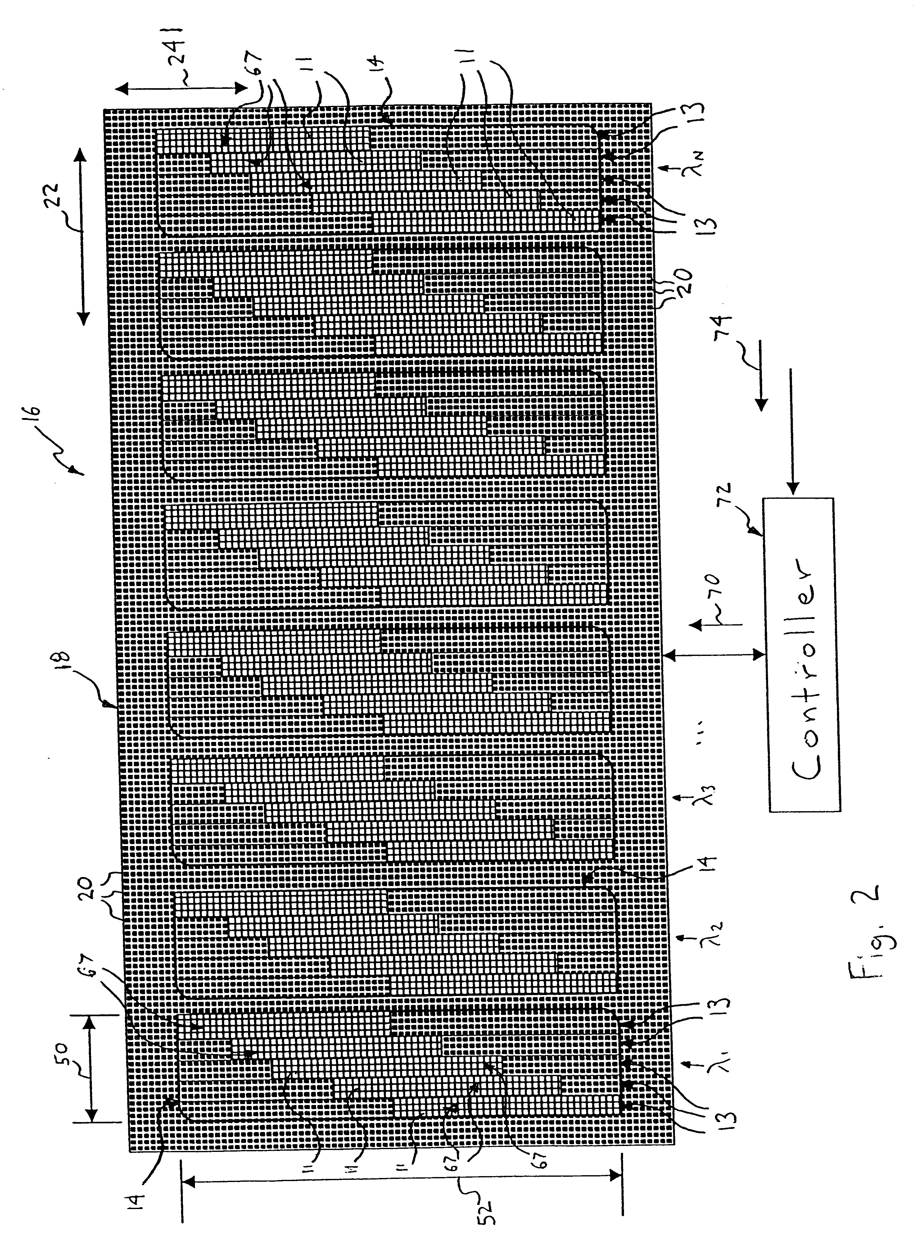
[0053]FIGS. 1 and 2 show a chromatic dispersion compensation device, generally indicated as 10, that selectively delays a respective portion 11 (FIG. 2) of a plurality of spectral bands or sections 13 of each respective optical channel 14 (i.e., a wavelength band of light) of an optical WDM input signal 12 to compensate each channel for chromatic dispersion. Each of the optical channels 14 of the input signal 12 is centered at a respective channel wavelength (λ1, λ2, . . . , λN). As will be described in greater detail hereinafter, the dispersion compensation device 10 includes a spatial light modulator 16 that comprises a micromirror device 18. The micromirror device includes an array of micromirrors 20 that effectively forms a two-dimensional diffraction grating that is mounted in a Littrow (retro-reflecting) configuration.

[0054]In FIG. 2, each optical channel 14 is dispersed onto the array of micromirrors 20 along a “spectral” axis or direction 22, and a “spatial” axis or directio...


PUM


Abstract

A chromatic dispersion compensation device selectively delays a respective portion of spectral sections of each respective optical channel of an optical WDM input signal to compensate each optical channel for dispersion compensation, and includes a spatial light modulator having a micromirror device with a two-dimensional array of micromirrors. The micromirrors tilt or flip between first and second positions in a “digital” fashion in response to a control signal provided by a controller in accordance with a switching algorithm and an input command. A collimator, diffraction gratings, and Fourier lens collectively collimate, disperse and focus the optical input channels onto the array of micromirrors. Each optical channel is focused onto micromirrors of the micromirror device, which effectively pixelates the optical channels. To compensate an optical channel for chromatic dispersion, a portion of the spectral sections of each channel is delayed a desired time period by tilting an array of mirrors (i.e., spectral array) disposed in each spectral section at different spatial positions on the micromirror device.

Description

CROSS REFERENCE TO RELATED APPLICATIONS[0001]This patent claims the benefit to U.S. Provisional Patent Application Ser. No. 60 / 332,318, filed Nov. 16, 2001, and is a continuation-in-part of U.S. patent application Ser. No. 10 / 115,647, filed Apr. 3, 2002, which claims the benefit of U.S. Provisional Patent Application Ser. No. 60 / 281,079, filed Apr. 3, 2001; U.S. Provisional Patent Application Ser. No. 60 / 311,002, filed Aug. 8, 2001; U.S. Provisional Patent Application Ser. No. 60 / 332,319, filed Nov. 16, 2001; U.S. Provisional Patent Application Ser. No. 60 / 365,741, filed Mar. 18, 2002; and U.S. Provisional Patent Application Ser. No. 60 / 365,461, filed Mar. 18, 2002; and is a continuation-in-part of U.S. patent application Ser. No. 10 / 120,617, filed Apr. 11, 2002, which claims the benefit of U.S. Provisional Patent Application Ser. No. 60 / 283,197, all of which are incorporated herein by reference in their entirety.BACKGROUND OF THE INVENTION[0002]1. Technical Field[0003]The present i...

Claims


Application Information

Patent Timeline
IPC IPC(8): G02B26/08G02B27/10G02B6/34G02B6/26H04J14/02G02B6/42H04Q11/00
CPCG02B6/262G02B6/266G02B6/29311G02B6/29394G02B6/29395G02B26/0833G02B26/0841G02B27/1086H04J14/0221G02B6/4226H04J14/021H04J14/0212H04J14/0213H04Q2011/0009H04Q2011/0026
Inventor MOON, JOHN A.KERSEY, ALAN D.DAWSON, JAY W.PINTO, JOSEPHDUNPHY, JAMES R.DAVIS, MICHAEL A.
Owner II VI DELAWARE INC
Learn More