Image-forming apparatus and image-forming method

a technology of image forming apparatus and image carrier, which is applied in the direction of electrographic process apparatus, instruments, optics, etc., can solve the problems of insufficient image quality, large image deterioration, and insufficient image quality, so as to reduce image deterioration due to heat propagation from the transfer means to the image carrier, reduce and avoid image deterioration due to transfer dust

Inactive Publication Date: 2005-08-23
RICOH KK
View PDF23 Cites 40 Cited by
  • Summary
  • Abstract
  • Description
  • Claims
  • Application Information

AI Technical Summary

Benefits of technology

[0018]It is therefore an object of the present invention, which was conceived in view of the above problems, to provide an image-forming apparatus and image-forming method which avoid toner deterioration and damage to apparatus due to heat, avoid the problems of the pressure-only method such as enlargement of apparatus, creases and image broadening, and suppress image deterioration due to transfer dust without using a capsule toner.
[0021]As the toner image can be transferred without using a capsule toner, image deterioration due to transfer dust can be avoided without using a capsule toner. Also, as the fixing means is provided separately from the transfer means, the heating temperature due to this transfer means is lower than that of the fixing means.
[0022]In this construction, in the transfer position, the toner image is only transferred by heat, so the toner image can be fixed by a fixing means at a higher heating temperature than the transfer means. Therefore, compared with the prior art heating simultaneous transfer and fixing method wherein transfer and fixing were performed simultaneously by the transfer means, the heating temperature of the transfer means can be set low. Consequently, image deterioration due to heat propagation from the transfer means to the image carrier can definitively be reduced. Further, compared with the prior art simultaneous pressure transfer and fixing method wherein transfer and fixing were performed simultaneously by pressure alone, the pressure in the transfer means can be set low. Hence, enlargement of apparatus, fixing creases and image broadening, etc. can be prevented. Herein, if the toner image is transferred from the latent image carrier to the transfer material and the heat supplied to the toner is lower than the glass transition temperature Tg of this toner, sufficient adhesion to this transfer material is no longer obtained. On the other hand, if it is higher than the softening temperature Tm, it fully adheres to the transfer material, but the latent image carrier and the surrounding developing means may be affected by heat, and the toner may solidify.

Problems solved by technology

It is particularly well-known that deterioration of the image is especially large during developing, transfer and fixing.
In the developing step, as toner adheres electrostatically to the photoconductor latent image due to the electric field surrounding the toner on the photoconductor, developing takes place over a larger area than the latent image or becomes blurred due to scratching of the carrier, and image deterioration of the electrostatic latent image occurs.
In recent years, this has been improved by the fineness and sphericity of toner and the fineness of the carrier, but it still does not give sufficient image quality.
However, dust and blurring occur electrostatically during intimate contact with the transfer paper before and after this transfer step, and image deterioration increases.
Also in the fixing step, deterioration may occur due to the spread of the toner image from melting of toner in the step wherein toner is fused with the transfer paper.
Further, when there is scatter in the amount of toner deposit on the transfer paper, scatter in the dot diameter or line width may increase, and deterioration may occur.
Of the aforesaid image deteriorations, the image deterioration in the transfer step is particularly large.
For this reason, a large stress acts on the toner at the photoconductor, developing apparatus and cleaning apparatus, and presents a major problem in practical applications.
Even if a cooling device is provided, damage to the photoconductor, the toner on the photoconductor and the developing apparatus, is unavoidable.
This requires a larger and heavier apparatus due to mechanisms and transfer paper transportation, and leads to fixing creases in the transfer paper and image broadening.
Due to these problems, simultaneous transfer and fixing only by pressure are not in practical use.
However, it is difficult to reconcile good developing and fixing properties for the capsule toner, and there is the drawback of high cost.

Method used


Image

  • Image-forming apparatus and image-forming method
  • Image-forming apparatus and image-forming method
  • Image-forming apparatus and image-forming method

Examples


examples i-1 to i-5

[0110]The method of manufacturing the toner will now be described.

[0111]

[Toner 1](Toner ingredients)Polyester resin82parts by weight(weight average molecular weight: 208000, Tg: 57)Polyethylene wax5parts by weight(molecular weight 900)Carbon black (Mitsubishi Chemical Corporation,12parts by weightNo. 44)Charge controlling agent (Spiron Black TR-H:1part by weightHodogaya Chemical Co., Ltd.)

[0112]The above ingredients were kneaded at 100° C. using a two-axis extruder, crushed in an air current mill, graded to a weight average particle diameter of 9.5 μm (weight average particle diameter / number average particle diameter=1.45), and mixed with 0.15% by weight of silica (R-972, Japan Aerogel) a Henschel mixer to obtain a toner.

[0113]The softening temperature of this toner was 98° C., the volume resistivity was 9.5×10⁸ Ω·cm, the average sphericity was 0.88, Tg was 58° C., the temperature at which the melt viscosity was 1000 PaS was 115° C., and the apparent density was 0.28 g / cc. A carrier...

example ii

[0156]Next, examples of using a low resistance toner will be described.

[0157]The Inventors manufactured 9 types of toner referred to as Developer A-Developer I, and output images using these toners. Specifically, the following 9 toner compositions, referred to as Composition A-Composition I, were prepared.

[0158]

[Composition A]Polyester resin:89 parts by weight(weight-average molecularweight: 325000, glass transitiontemperature Tg: 67.5° C.)Polyethylene wax (molecular weight 900): 5 parts by weightMagnetite particulates:50 parts by weightCarbon black: 3 parts by weight(Ketchen Black EC, Ketchen Black International)Charge controlling agent 1 part by weight(Spiron Black TR-H, HODOGAYACHEMICAL CO., LTD., hereafter idem):[Composition B]Identical to Composition A, except that carbon blackwas changed to 5 parts by weight.[Composition C]Polyester resin:89 parts by weight(weight-average molecular weight: 325000,glass transition temperatureTg: 67.5° C.)Polypropyrene wax: 3 parts by weight(mol...

example iii

[0180]Next, examples of an image-forming apparatus and an image forming method according to the present invention, wherein a pressure of 10-100N / cm2 is applied between the transfer roller and photoconductor, will be described.

[0181]As the developer used in Example III, 10 types of developers A-J were prepared.

[0182]

Developer A(Toner ingredients)Polyester resin82 parts by weight(weight average molecular weight: 52000,Tg: 54° C.)Polyethylene wax 5 parts by weight(molecular weight 900)Carbon black (Mitsubishi Chemical12 parts by weightCorporation, No. 44)Charge controlling agent (Spiron 1 part by weightBlack TR-H: Hodogaya Chemical Co.,Ltd.)

[0183]The above ingredients were kneaded at 80° C. using a two-axis extruder, crushed in an air current mill, graded to a weight average particle diameter of 9.5 μm (weight average particle diameter / number average particle diameter=1.45), and mixed with 0.25% by weight of silica (R-972, Japan Aerogel) using a Henschel mixer to obtain the following t...


PUM


Abstract

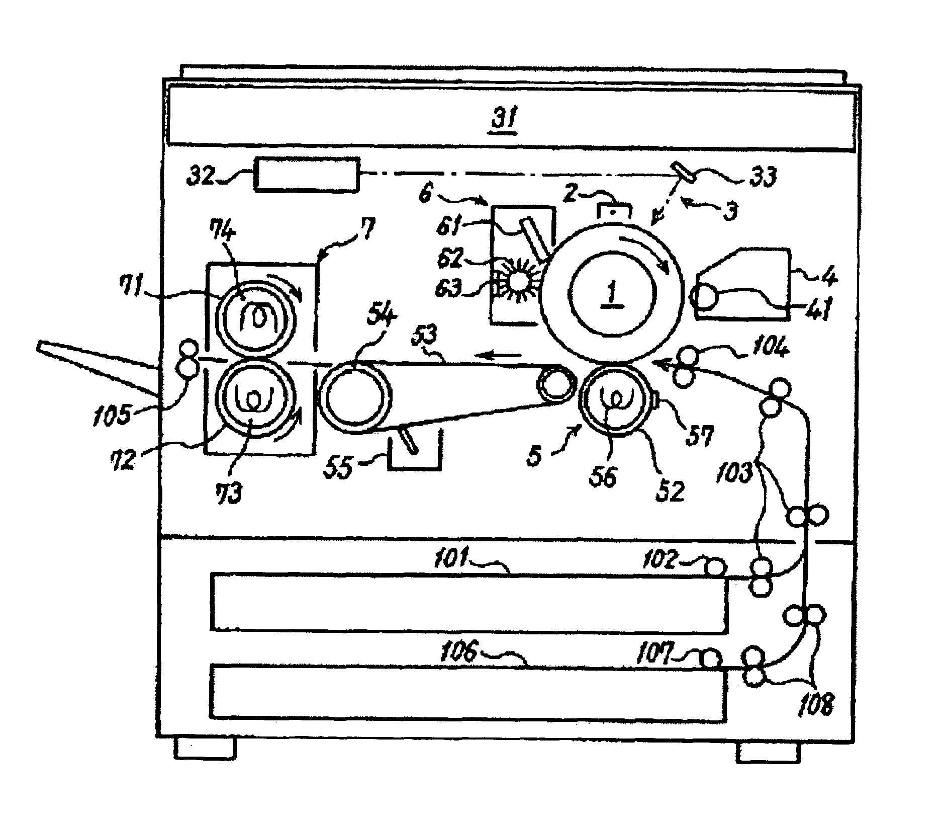
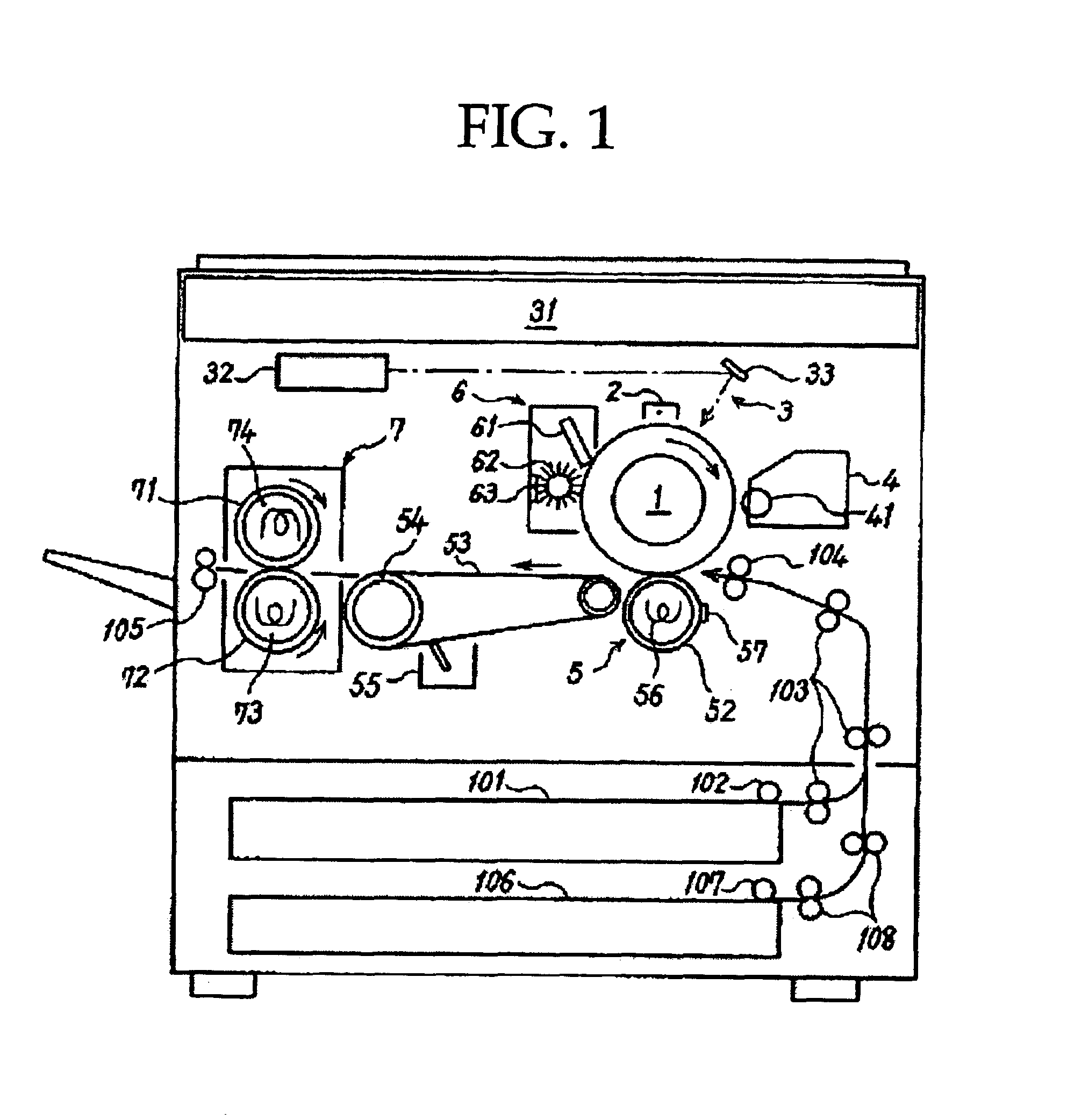
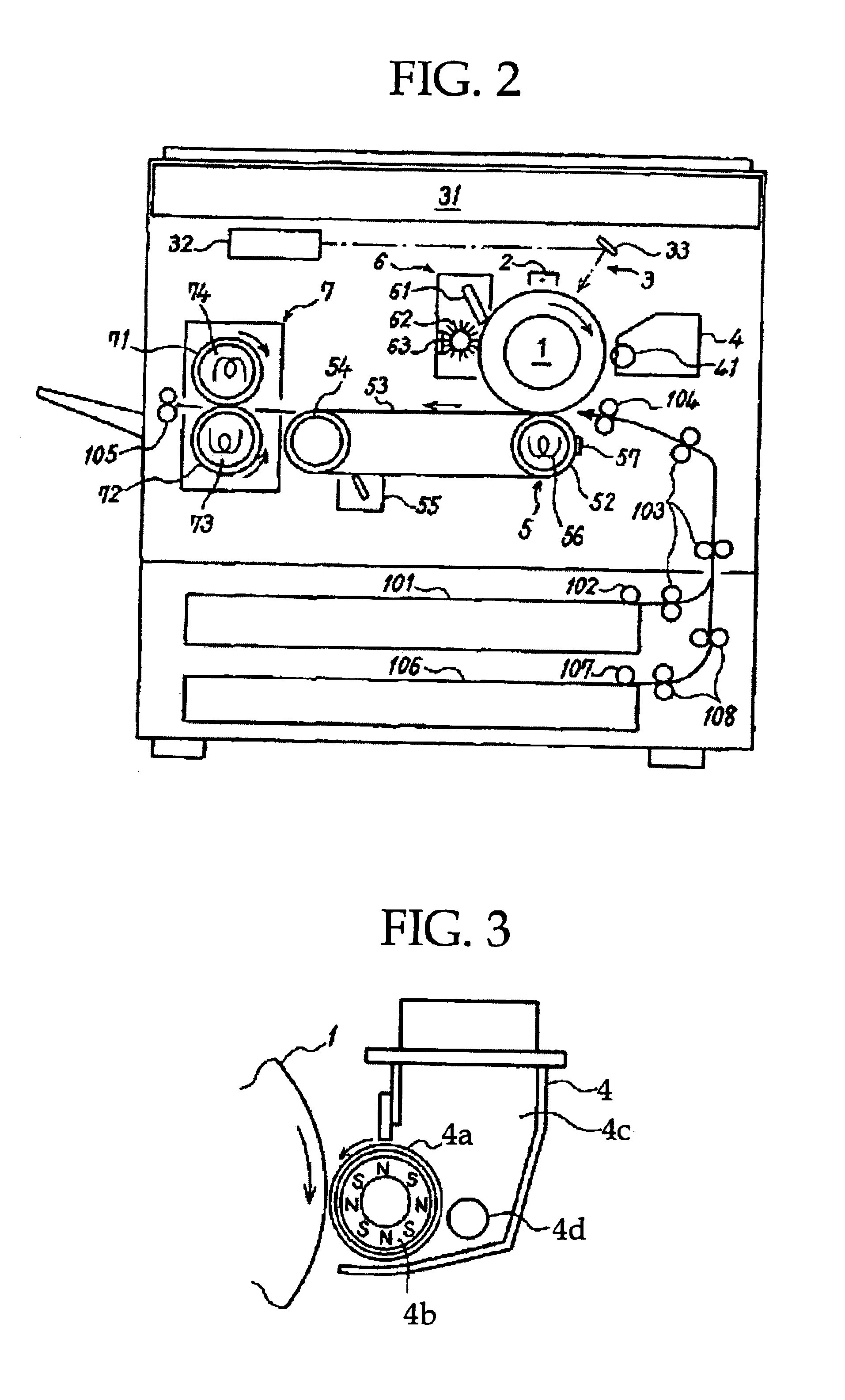
In a copier which is an image-forming apparatus comprising a photoconductor 1, a developing apparatus 4, transfer apparatus 5 which transfers a toner image formed on the photoconductor 1 to a transfer material by heat and pressure using a transfer roller 52, and a fixing apparatus which fixes the toner image transferred to the transfer material, on the transfer material, a heater 56, temperature detection apparatus 57 and temperature control apparatus are provided which controls the temperature to within a range of from the glass transition temperature (Tg) to the softening temperature (Tm) of the toner, and lower than the fixing temperature of the fixing apparatus 7.

Description

BACKGROUND OF THE INVENTION[0001]1. Field of the Invention[0002]The present invention relates to an image-forming apparatus such as a copier, a facsimile and a printer, in particular an image-forming apparatus comprising a latent image carrier which forms a latent image on its surface, a developing means to render this latent image into a visible image as a toner image by adhesion of toner, a transfer means which transfers the toner image formed on this latent image carrier to a transfer material without using an electrostatic transfer method, and a fixing means which fixes the transferred toner image on the transfer material by heat and pressure. The present invention also relates in particular to an image-forming method using this image-forming apparatus.[0003]2. Description of the Related Art[0004]In the prior art, in this kind of image-forming apparatus, an electrophotographic image-forming method is used wherein an image is formed in a large number of steps, such as a latent im...

Claims


Application Information

Patent Timeline
Patent Type & Authority Patents(United States)
IPC IPC(8): G03G15/20
CPCG03G15/2064
Inventor SUZUKI, KOJIAOKI, MITSUOHIGUCHI, HIROTONAKAYAMA, SHINYAKONDO, MAIKOSHU, BINGKOICHI, YASUSHIKASAI, TADASHITAKAHASHI, YUTAKA
Owner RICOH KK
Why Eureka
Try Eureka