Reinforced composite system for constructing insulated concrete structures

Inactive Publication Date: 2005-08-30
DUNN DANIEL D +1
View PDF60 Cites 154 Cited by
  • Summary
  • Abstract
  • Description
  • Claims
  • Application Information

AI Technical Summary

Benefits of technology

[0009]The primary object of this invention is to provide a system for constructing Insulated concrete structures that is user friendly, is durable enough to withstand handli

Problems solved by technology

Known art systems are limited in many respects due to the materials used, the manufacturing process and the configuration of the ties, webs and connectors.
The EPS foam doesn't adhere to the ties and webs when using molded-in configurations causing a weak point in the panels at each tie or web location.
In the slide-in configurations the molded slots penetrate deeply into the panels also creating a weakness at each penetration.
The panels are manufactured in small units approximately 12 inches to 16 inches in height and 36 inches to 48 inches in length, the size being limited by the strength of the low density EPS and the prohibitive cost of larger molds and more expensive machinery to contain the molds during the high pressure steam expansion process.
EPS has a relatively low R-value per inch and the poor structural characteristic make it prone to damage during material handling and construction.
These restrictive configurations, and the close spacing of the ties, webs and connectors, create a structural weakness in the wall caused by the number of penetrations through the concrete, in addition they inhibit the natural flow of the concrete during placement increasing the difficulty of pouring the walls and causing honey comb in the concrete.
The inherent weakness of the EPS makes it very difficult to vibrate the walls to increase

Method used


Image

  • Reinforced composite system for constructing insulated concrete structures
  • Reinforced composite system for constructing insulated concrete structures
  • Reinforced composite system for constructing insulated concrete structures

Examples


first embodiment

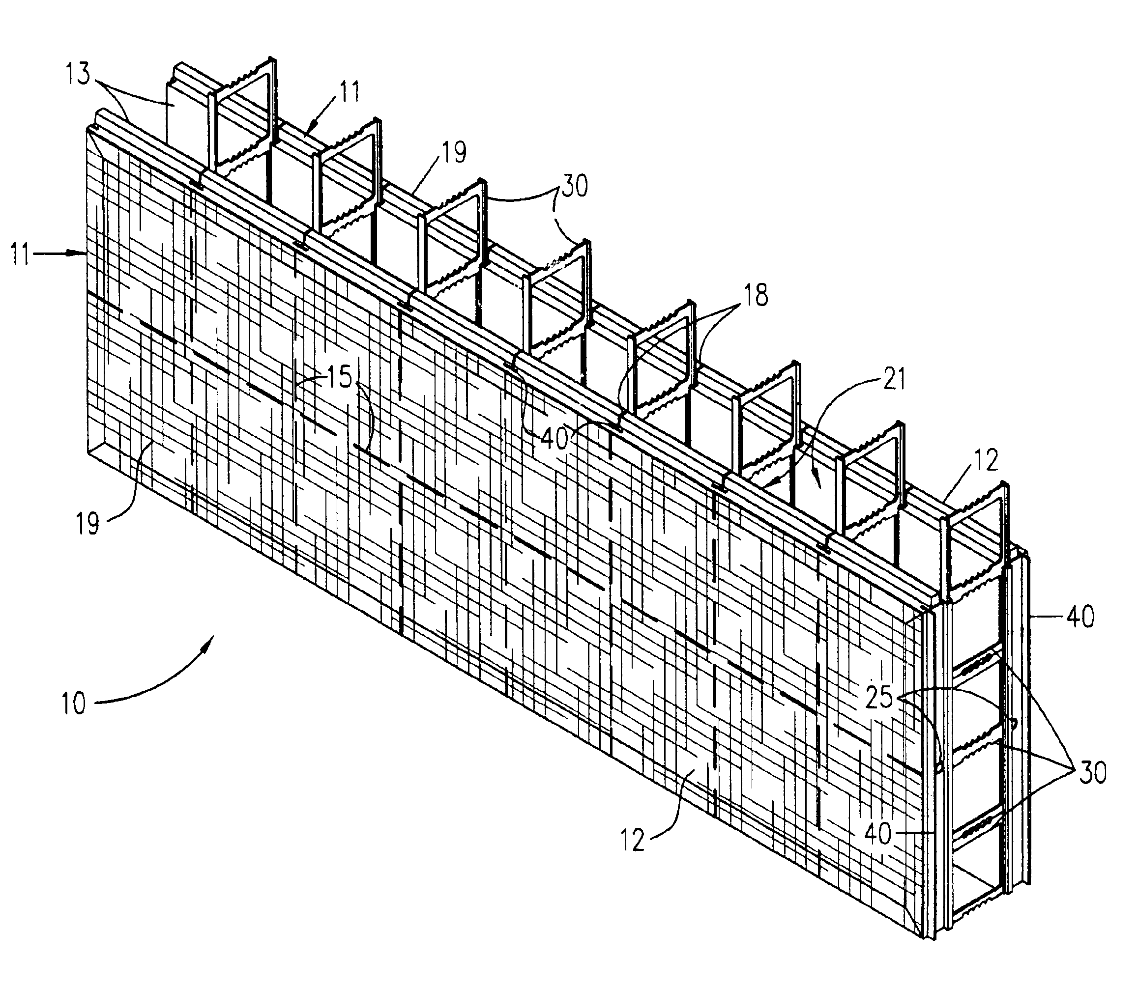
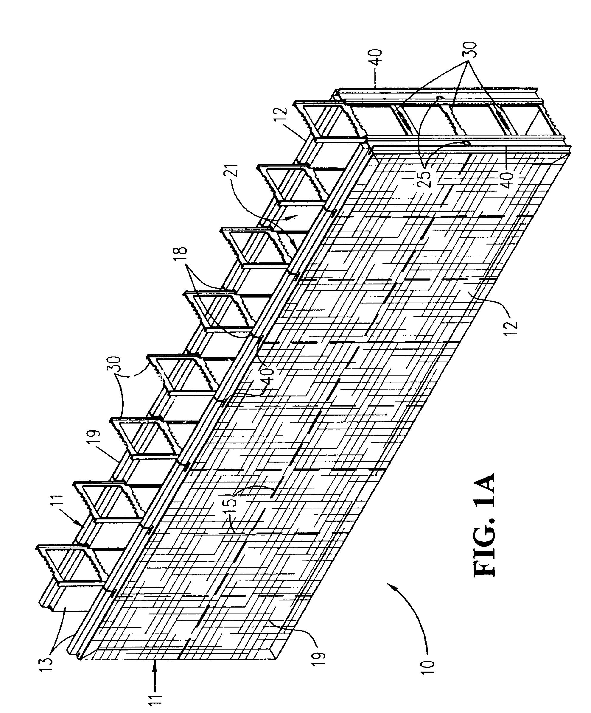
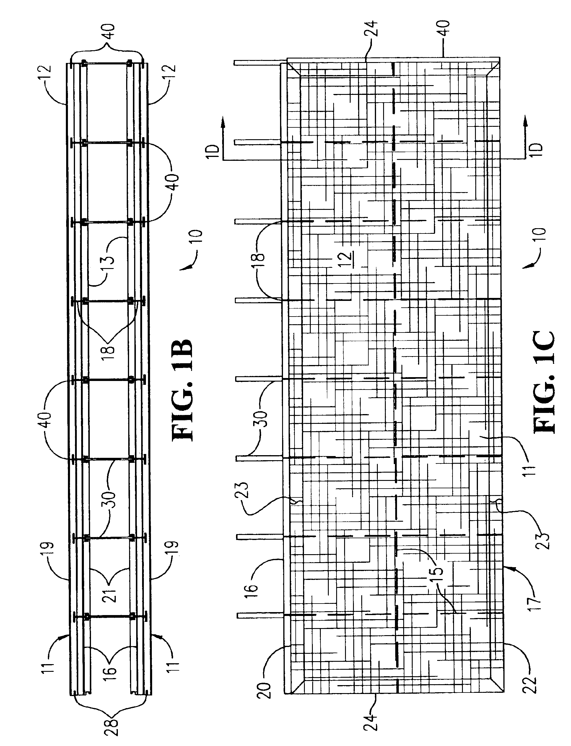
[0051]Turning now to the drawings, there is shown in FIGS. 1A-9a reinforced composite forming system for constructing insulated concrete structures. the present invention a form unit 10, as shown in FIGS. 1a-1d comprises panels 11 having outside surfaces 12 and inside surfaces 13, top 20, bottom 22 and end edges 24. Studs 40 and a horizontal stiffener 25 are embedded in each panel. The panels 11 are placed in an opposing and parallel relationship. Spreaders 30 are located at each stud 40, extending between and engaging the studs 40 in opposing panels 11 thereby creating a form 10 with a cavity between the panels 11. The cavity is filled with fluid concrete to create a structure. The structural design of the concrete structures is based on the Uniform Building Code and other accepted building codes.

[0052]The panels 11 comprise a closed cell foam plastic core 14 between an outside reinforcement layer 19 and an inside reinforcement layer 21. The reinforcement layers extend substantiall...

second embodiment

[0053]A means of interlocking the panels is provided comprising a tongue 16 that extends from and is parallel to the top edge 20 of each panel 11, and a complementary groove 17 recessed into and parallel to the bottom edge 22 of each panel 11. The inside reinforcement layer 21 of each panel extends around the tongue 16 and into the groove 17, defining and reinforcing them. The embedded studs 40 extend through the groove 17 in each panel 11 and the tongue 16 has slots 18 that correspond with the studs 40 so that when the forms 10 are stacked the studs 40 engage the slots 18 in the tongue 16 of the row of forms below, aligning studs 40 of adjacent panels 11 vertically. In a second embodiment a preformed unit is used to form the tongue 16 and groove 17. The preformed tongue 110 and groove 111 units are preferably made of plastic with appendages 115 protruding into the groove unit 111 and corresponding with the spacing of the studs 40. The appendages 115 in the groove unit 111 of each p...


PUM


Abstract

A reinforced composite system for constructing insulated concrete structures comprising, panels having a foam plastic core between outside and inside reinforcement layers, reinforcement layers substantially strengthen the panels during material handling and construction, greatly reducing deflection of the panels between studs when placing concrete allowing walls to be filled in one lift. Panels are placed horizontally in an opposing and parallel spaced-apart relation. Opposing panels are placed end to end in rows and stacked vertically, rows of panels being staggered from each other so panel ends in adjacent rows do not line up vertically. Vertical studs are embedded in panels extending the full height of the panels, each stud having a flange for receiving mechanical fasteners and groove for receiving spreaders. A plurality of spreaders at each stud location extend between opposing panels and slidably engaging the studs in opposing panels. Spreaders are stacked vertically in such a manner as to engage studs half their height above and below the horizontal joints between rows of panels. Each spreader has opposing flanges connected by horizontal members, horizontal members having multiple formations, when spreaders are stacked the formations compliment each other allowing wall reinforcement bars to be restrained in any preferred location. Hollow horizontal stiffeners may be utilized to accommodate electrical wiring. Locations of vertical studs are shown by markings on the exterior of panels. Hinged corner forms and bearing ledge forms can be shipped flat and rotated into position on site.

Description

CROSS REFERENCES TO RELATED APPLICATION[0001]This is a continuation in part of Ser. No. 09 / 803,205, filed Mar. 09, 2001 U.S. Pat. Pat. No. 6,647,686 and titled “System for Constructing Insulated Concrete Structures.”BACKGROUND OF THE INVENTION[0002]The present invention relates to construction using Insulating Concrete forming Systems (ICFS), and more particularly to a new reinforced composite system for constructing insulated concrete structures.[0003]Insulating Concrete Forming Systems (ICFS), which are currently known, act as forms for the construction of concrete walls, the end benefit is a wall which is already insulated and ready for the application of exterior and interior finish materials. The known ICFS currently in use comprise a pair of foam plastic panels connected by a plurality of ties or connectors. The panels are molded from expanded polystyrene (EPS) beads providing low density foam plastic panels which are used as a form to contain the concrete during placement. Th...

Claims


Application Information

Patent Timeline
IPC IPC(8): E04B2/86
CPCE04B2/8641E04B2002/867
Inventor DUNN, DANIEL D.DUNN, DAVID C.
Owner DUNN DANIEL D
Why Eureka
Try Eureka