Illumination apparatus for planar display device

Inactive Publication Date: 2005-08-30
SAMSUNG DISPLAY CO LTD
View PDF9 Cites 32 Cited by
  • Summary
  • Abstract
  • Description
  • Claims
  • Application Information

AI Technical Summary

Benefits of technology

[0022]The above-described illumination apparatus includes an air lens for reducing the emission angle of light, thereby reducing the loss of luminous intensity. As shown in FIG. 2, luminous intensity decreases as the emission angle of light increases. Accordingly, in an illumination apparatu

Problems solved by technology

Light emitted at arbitrary angles other than a right angle with respect to the plane of a light guide plate causes loss of light incident upon a liquid crystal panel, thereby degrading luminance and affecting the viewing angle of a screen.
In an illumination apparatus for planar d

Method used


Image

  • Illumination apparatus for planar display device
  • Illumination apparatus for planar display device
  • Illumination apparatus for planar display device

Examples


first embodiment

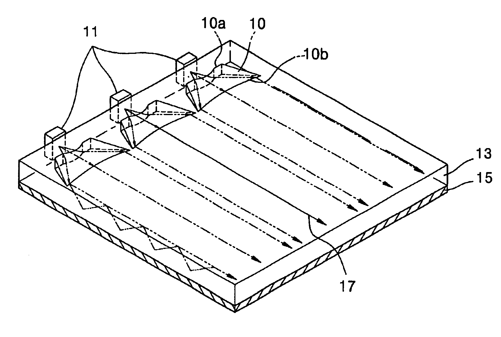
[0037]Referring to FIG. 5, in an illumination apparatus for planar display devices, according to the present invention, dot light sources 11 are aligned on one side of a light guide plate 13 having a hologram 15 formed on its bottom surface. First air lenses 10 are formed adjacent to the dot light sources 11, within the light guide plate 13. The hologram 15 uniforms the luminance and luminous intensity distributions of light emitted from the light guide plate 13, and may be formed on the upper surface of the light guide plate 13. Instead of the hologram 15, an optical means for performing diffraction, such as mechanical unevenness, can also be formed on the top or bottom surface of the light guide plate 13. Or, such an optical means may not be formed on the light guide 13.

[0038]An LED or LD is used as the dot light sources 11. In order to illuminate a planar display device, such as an LCD, the plurality of dot light sources 11 are aligned adjacent to the light guide plate 13 at pred...

second embodiment

[0049]FIG. 9 is a perspective view of an illumination apparatus for planar display devices, according to the present invention. Referring to FIG. 9, second air lenses 20 are installed adjacent to the dot light sources 11, within the light guide plate 13. Each of the second air lenses 20 includes first and second refraction facets 20a and 20b. The first refraction facet 20a increases the radiation angle of light emitted from the dot light sources 11 and has the same shape as the outer facet of a cylindrical lens The second refraction facet 20b has the same shape as the lens facet of a cylindrical lens and reduces the radiation angle by refracting incident light whose radiation angle has been increased by the first refraction facet 20a, so that light travels parallel to the optical axis 17. The first and second refraction facets 20a and 20b are symmetrical to each other The second refraction facet 20b has a larger curvature radius than that of the first refraction facet 20a.

[0050]A d...

third embodiment

[0052]FIG. 10 is a perspective view of an illumination apparatus for planar display devices, according to the present invention. Referring to FIG. 10, third air lenses 30 are installed adjacent to the dot light sources 1 within the light guide plate 13. Each of the third air lenses 30 includes first and second refraction facets 30a and 30b, which are symmetrical to each other and have the same shape as the lens facet of a Fresnel lens. The second refraction facet 30b has a larger curvature radius than that of the first refraction facet 30a. Light emitted from the dot light sources 11 are refracted while transmitting the second or third air lenses 20 or 30, such that the light travels parallel to the optical axis 17.

[0053]Like the first and second embodiments of the present invention, the illumination apparatus according to the third embodiment also has a diffraction element, such as a hologram, formed on the top or bottom surface of the light guide plate 13, so that the intensity di...


PUM


Abstract

An illumination apparatus for planar display devices, including an optical element for making light travel parallel to an optical axis, is provided. The illumination apparatus includes a dot light source for radiating light, and a light guide plate having the optical element. The optical element is composed of a first refraction facet, which is adjacent to the dot light source and increases the emission angle of the light, and a second refraction facet, which is isolated a predetermined distance from the first refraction facet while facing the first refraction facet and reduces the emission angle of the light. In this structure, the light travels parallel to the optical axis. In the illumination apparatus, the emission angle of incident light is reduced, preferably, the light travels parallel to the optical axis. Therefore, areas not reached by light, between adjacent dot light sources, are eliminated, and light is uniformly incident upon a hologram so that the luminance and intensity of light emitted from the light guide plate are uniformly distributed.

Description

BACKGROUND OF THE INVENTION[0001]1. Field of the Invention[0002]The present invention relates to the field of illumination apparatuses for planar display devices, and more particularly, to an illumination apparatus for planar display devices, the illumination apparatus making incident light travel parallel to an optical axis by reducing the emission angle of the incident light.[0003]2. Description of the Related Art[0004]Generally, a planar display device, such as a liquid crystal display, requires an illumination apparatus to uniformly illuminate liquid crystal.[0005]FIG. 1 is a perspective view of a conventional illumination apparatus for planar display devices, the illumination apparatus including a light guide plate using a hologram The illumination apparatus of FIG. 1 uses dot light sources, such as laser emitting diodes (LEDs) 41.[0006]Referring to FIG. 1, the plurality of LEDs 41 are aligned on one side of a light guide plate 43, and light emitted from the LEDs 41 is diffused...

Claims


Application Information

Patent Timeline
IPC IPC(8): F21V8/00G02B6/00F21Y101/02G02F1/13357
CPCG02B6/002G02B6/0068G02F1/1335
Inventor CHOI, JIN-SEUNGCHOI, HWAN-YOUNGMIN, JEE-HONGLEE, SU-MIKIM, JIN-HWANLEE, MOON-GYU
Owner SAMSUNG DISPLAY CO LTD
Why Eureka
Try Eureka