Ultrathin form factor MEMS microphones and microspeakers

a technology of micro-electromechanical systems and microphones, applied in the field of processing techniques for forming ultra-thin devices, can solve the problems of slow venting formation and small vent diameter, and achieve the effect of reducing the thickness of the substra

Inactive Publication Date: 2005-08-30
AKUSTICA
View PDF19 Cites 70 Cited by
  • Summary
  • Abstract
  • Description
  • Claims
  • Application Information

AI Technical Summary

Problems solved by technology

Forming of vents by this technique is slow in that several hundred microns of substrate may need to be etched to reach the chamber beneath the sealed mesh and the diameter of the vent is small compared to its depth.
Additionally, there are registration problems in that it is necessary to work from the back side of the substrate where there are no landmarks, and hundreds of microns may need to be etched to reach a chamber that may measure in the tens of microns.

Method used


Image

  • Ultrathin form factor MEMS microphones and microspeakers
  • Ultrathin form factor MEMS microphones and microspeakers
  • Ultrathin form factor MEMS microphones and microspeakers

Examples


Embodiment Construction

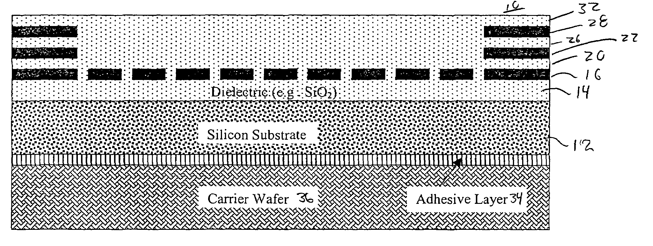
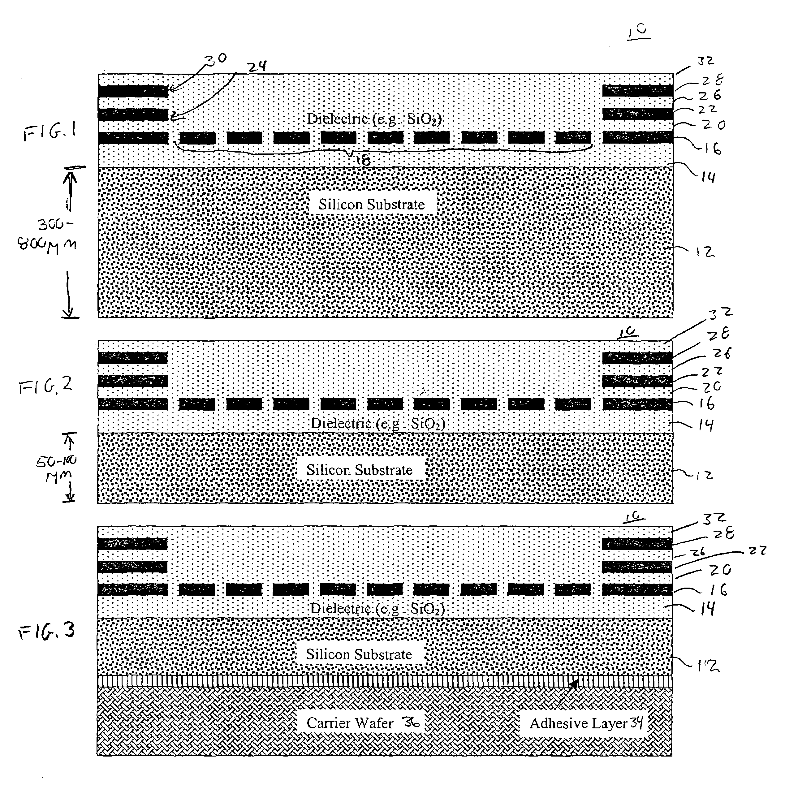
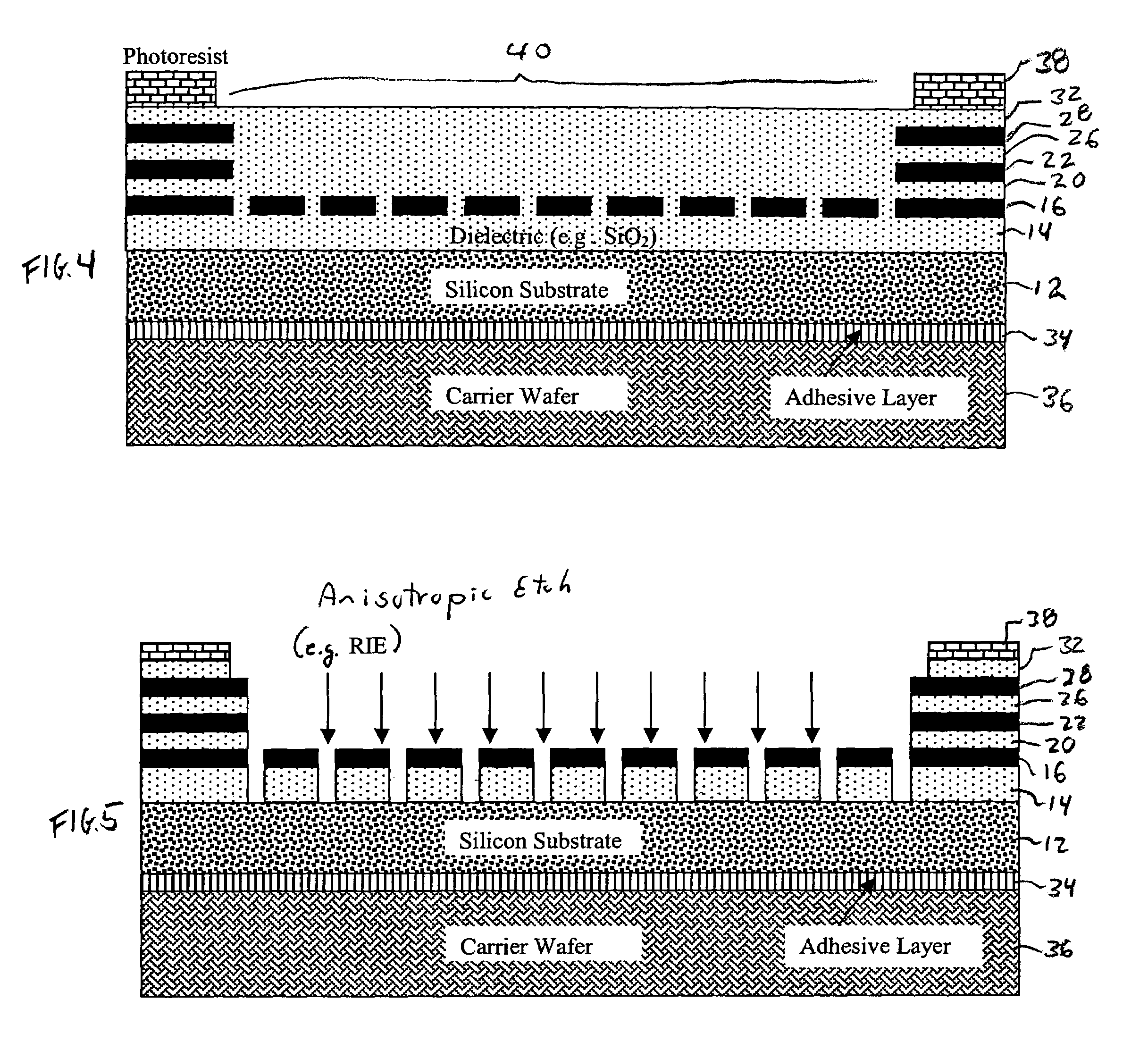
[0050]A first embodiment of the present disclosure is illustrated in conjunction with FIGS. 1–9. In FIG. 1, a wafer 10 (a portion of which is seen in FIG. 1) is received from a CMOS foundry. Those of ordinary skill in the art will recognize the wafer carries a plurality of devices, one of which is shown in FIG. 1. At the CMOS foundry, a silicon substrate 12 has been processed so as to form alternating layers of, for example, a dielectric material and a metal. The wafer 10 illustrated in FIG. 1 has a first layer of dielectric material 14 carrying a first metal layer 16. The first metal layer 16 has been patterned such that a portion thereof forms a micro-machined mesh 18. Formed on the first metal layer 16 is a second layer of dielectric 20. The second layer of dielectric 20 carries a second metal layer 22 which has been patterned to have an opening 24 formed therein. The second metal layer 22 carries a third layer of dielectric 26. The third layer of dielectric 26 carries a third la...


PUM


Abstract

A process comprises reducing the thickness of a substrate carrying a plurality of devices, with at least certain of the devices having a micro-machined mesh. A carrier wafer is attached to the back side of the substrate and the fabrication of the devices is completed from the top side of the substrate. Thereafter the plurality of devices is singulated. Various alternative embodiments are disclosed which demonstrate that the thinning of the wafer may occur at different times during the process of fabricating the MEMS devices such as before the mesh is formed or after the mesh is formed. Additionally, the use of carrier wafers to support the thinned wafer enables process steps to be carried out on the side opposite from the side having the carrier wafer. The various alternative embodiments demonstrate that the side carrying the carrier wafer can be varied throughout the process.

Description

BACKGROUND[0001]The present disclosure is directed generally to micro-electro-mechanical systems (MEMS) devices and, more particularly, to processing techniques for forming ultrathin devices.[0002]The ability to form moving parts measured in microns has opened up a huge range of applications. Such moving parts typically take the form of a beam or mesh that may form, for example, a variable capacitor, switch, or other component. The recent ability to seal micro-machined meshes has lead to the fabrication of microphones and microspeakers. See, for example, International Publication No. WO / 01 / 20948 A2 published 22 Mar. 2001, entitled MEMS Digital-to-Acoustic Transducer With Error Cancellation, the entirety of which is hereby incorporated by reference.[0003]A sealed mesh can function as a movable plate of a variable capacitor, and therefore can operate as a microspeaker or microphone. For a sealed mesh to operate as a microspeaker or microphone, the device needs to be able to push air t...

Claims


Application Information

Patent Timeline
Patent Type & Authority Patents(United States)
IPC IPC(8): H01L21/02H01L21/30H01L21/00H01L21/46H04R19/00
CPCB81C1/00182H04R19/005Y10S438/977
Inventor ZHU, XUCIFERNO, RAYMOND A.
Owner AKUSTICA
Why Eureka
Try Eureka