Inductively-coupled plasma torch

a plasma torch and inductive coupling technology, which is applied in the direction of particle separator tube details, instruments, manufacturing tools, etc., can solve the problems of deteriorating the degree of separation of the compound separated by the gas chromatograph, the inability to analyze the high-boiling point compound, and the risk of electric shock, so as to achieve smooth conveying of make-up gas

Inactive Publication Date: 2005-08-30
NAT INST OF ADVANCED IND SCI & TECH +1
View PDF10 Cites 24 Cited by
  • Summary
  • Abstract
  • Description
  • Claims
  • Application Information

AI Technical Summary

Benefits of technology

[0010]A purpose of the present invention is therefore to provide an inductively-coupled plasma torch wherein the capillary tube is held with stability coaxially with the injector tube, make-up gas is conveyed through the torch smoothly, and the position of the downstream end portion of the capillary tube in the axial direction may be adjusted easily.
[0012]The cylindrical guide has a through hole in its center part through which the capillary tube is passed, and passage grooves or passage holes for conveying make-up gas. The make-up gas tube is inserted coaxially within the body of the injector tube. The guide is disposed between the make-up gas tube and the downstream end portion of the injector tube. Because of this constitution, the capillary tube is fixed coaxially with the injector tube, and make-up gas flows to the downstream end of the injector tube smoothly.
[0013]The means for conveying make-up gas, the passage grooves, or the passage holes are provided aside from the through hole provided through the center of the guide. The passage grooves are formed to have a cross section shaped like, e.g., a U or V letter when seen from the axial direction, and are provided on the circumferential surface of the guide so as to extend to the axial direction. Because of this constitution having the passage grooves, make-up gas flows to the end portion of the injector tube smoothly.
[0017]The guide may be disposed near the outlet of the make-up gas tube, that is, between the downstream end of the make-up gas tube and the downstream end portion of the injector tube, being simply held by the injector tube, or being fused to the downstream end of the make-up gas tube or the downstream end portion of the injector tube. In the latter case, the number of components for the assembly may be reduced and the assemblability may be improved.
[0020]When the outer diameter of the guide is larger than the inner diameter of the downstream end portion of the injector tube, flow paths for make-up gas may be provided on the end face of the guide facing the downstream end portion of the injector tube, and / or the end face of the downstream end portion of the injector tube facing the guide. The flow paths are formed with protrusions or grooves provided on the end face of the guide facing the downstream end portion of the injector tube, and / or the end face of the downstream end portion of the injector tube facing the guide. Because of this constitution, the guide and the injector tube do not come in intimate contact with each other all over the circumferential direction also at the portion overlapped in the radial direction, and thereby make-up gas may be conveyed smoothly.
[0021]Flow paths for make-up gas may be provided on the axial end face of the guide facing the make-up gas tube, and / or the axial end face of the make-up gas tube or thermal homogenizing pipe facing the guide. The flow paths are formed with protrusions or grooves provided on the axial end face of the guide facing the make-up gas tube, and / or the axial end face of the make-up gas tube or thermal homogenizing pipe facing the guide. Because of this constitution, the make-up gas tube or thermal homogenizing pipe and the guide do not come in intimate contact with each other all over the circumferential direction at the contact portion, and thereby make-up gas may be conveyed smoothly.

Problems solved by technology

(1) In an inductively-coupled plasma torch which increases the temperature of the sample-introducing tube therein by heat conduction, since it is difficult to keep the temperature of the sample-introducing tube even, the nearer a portion of the end of the sample-introducing tube is to its end, the more the temperature of the portion decreases and the high-boiling point compound condenses. For this reason, it becomes impossible to analyze the high-boiling point compound, and the degree of separation of the compound separated by the gas chromatograph deteriorates.
(2) In an inductively-coupled plasma torch where the sample-introducing tube is heated by feeding an electric current directly through it, a large current flows through it because of the low electric resistance of the metal, thereby causing the great risk of electric shock
(3) In an inductively-coupled plasma torch which increases the temperature of the sample-introducing tube by heat conduction, as well as an inductively-coupled plasma torch which feeds an electric current through the sample-introducing tube, if the sample-introducing tube is brought too near to the inductively-coupled plasma, electric discharge occurs and background signals increase, and furthermore the sample-introducing tube damages heavily.
(4) In any one of the inductively-coupled plasma torches stated above, it is difficult to locate the sample-introducing tube on the center axis of the inductively-coupled plasma torch, that is, coaxially with the inductively-coupled plasma torch, and hence if the high-boiling point compound out of the sample-introducing tube is not introduced into the center part of the inductively-coupled plasma, the sensitivity or accuracy of analysis for the high-boiling point compound deteriorates.
Furthermore, in the conventional ones, since the components for disposing the capillary tube coaxially with the sample-introducing tube are easy to be damaged, and the capillary tube is easy to move within the injector tube due to the pressure of the make-up gas, it has been difficult to correctly adjust the position of the capillary tube in the axial direction.

Method used


Image

  • Inductively-coupled plasma torch
  • Inductively-coupled plasma torch
  • Inductively-coupled plasma torch

Examples


embodiments

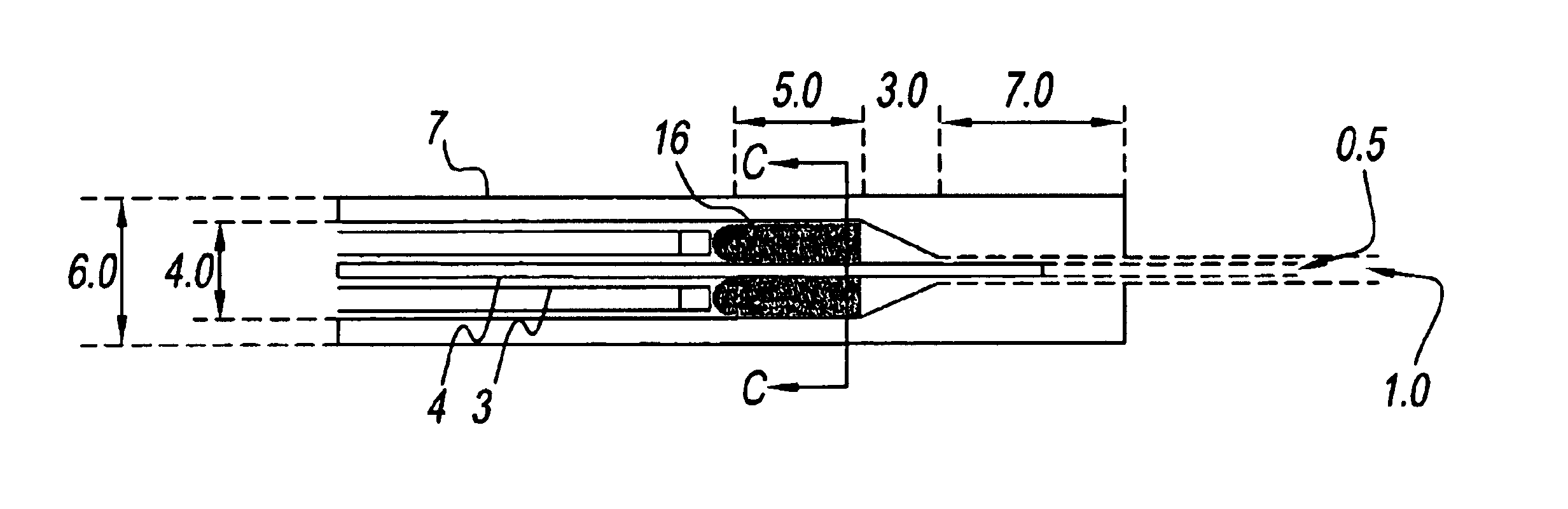
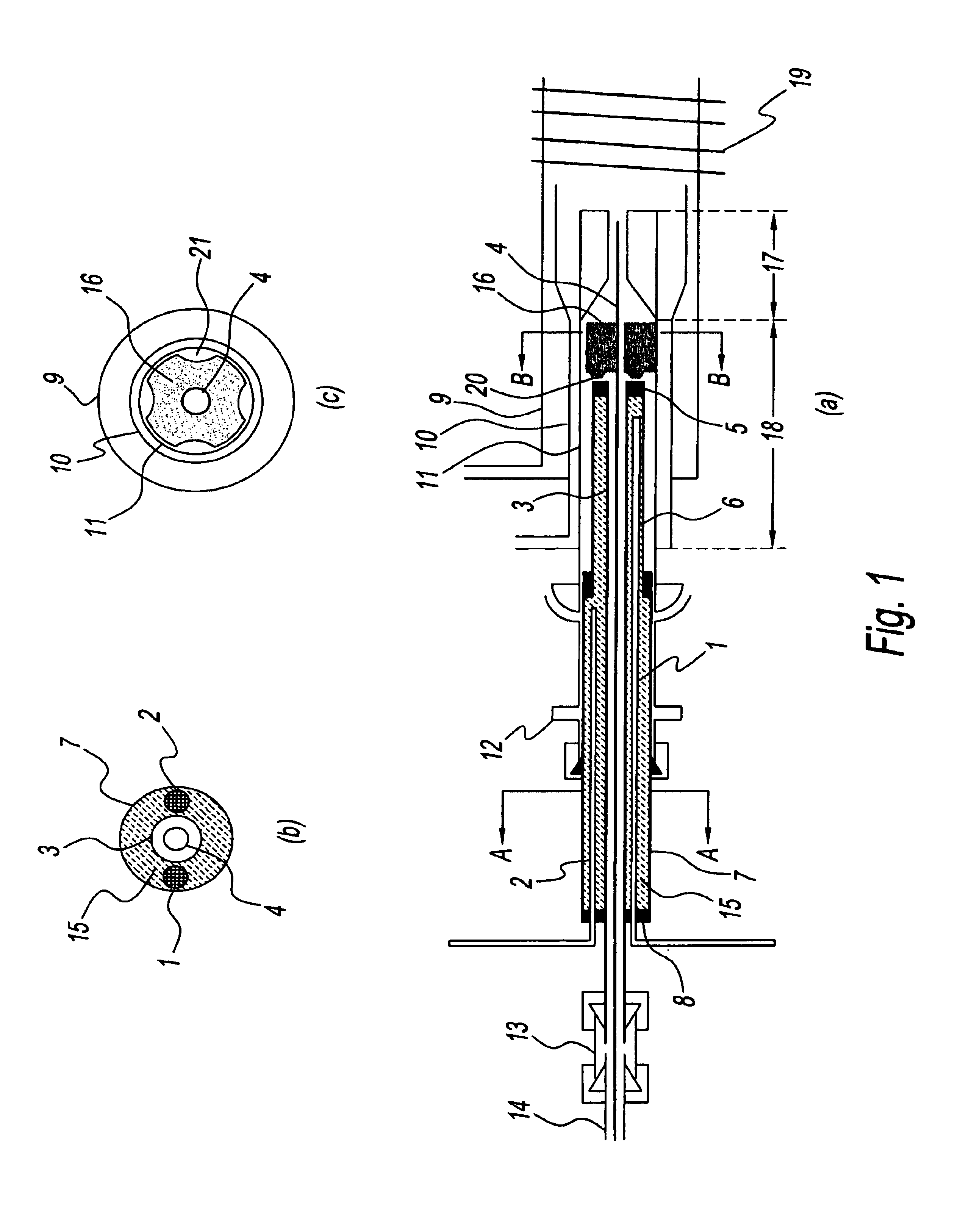
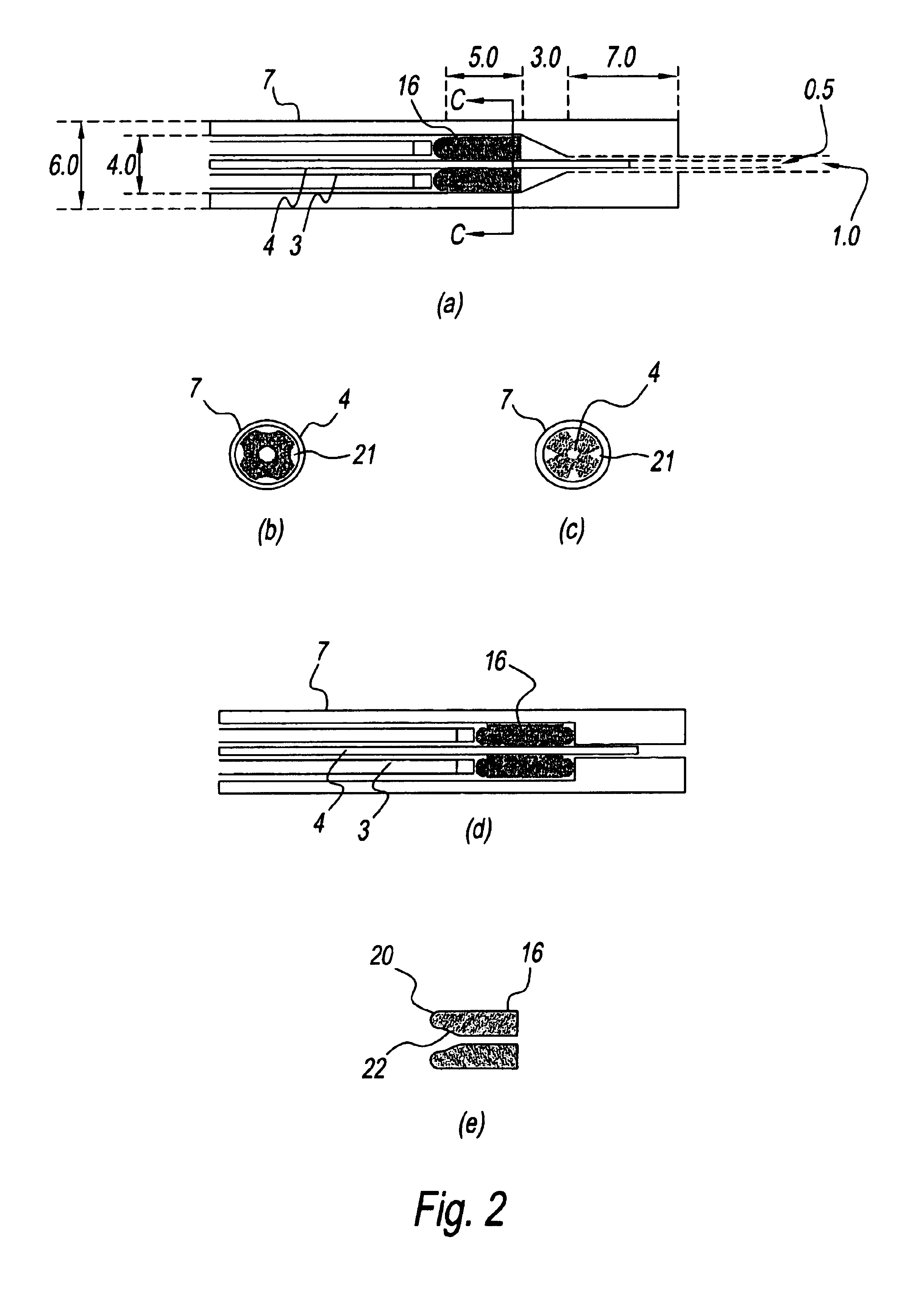
[0058]Furthermore, the present invention will be described in more detail with a more specific embodiment. In this embodiment, as a capillary tube 4 for introducing gaseous molecules, for example, a silica capillary tube used for a gas chromatograph is used, the inner surface of which is inactivated and which has an inner diameter of 0.32 mm and an outer diameter of about 0.5 mm, while a capillary tube made of other material or having other inner diameter or outer diameter may be used if it has high heat resistance and its inner surface is inactivated. And, as a metallic make-up gas tube 3, e.g., a stainless steel tube having an outer diameter of 1.59 mm and an inner diameter of 1.00 mm is used, while a stainless steel tube having a size close to this may be used. One end of the metallic tube 3 is connected to the metallic tube 14 extending from a high-temperature source by a connector 13. As a matter of course, this connecting portion is heated and thermally homogenized by a well-k...


PUM

PropertyMeasurementUnit
inner diameteraaaaaaaaaa
temperatureaaaaaaaaaa
lengthaaaaaaaaaa

Abstract

An inductively-coupled plasma torch capable of holding a capillary tube coaxially with an injector tube and conveying make-up gas smoothly is provided. The inductively-coupled plasma torch of the present invention includes a guide which is held near the end portion of the injector tube, and has a through hole for holding the capillary tube coaxially with the injector tube, and means for conveying make-up gas.

Description

FIELD OF THE INVENTION[0001]The present invention relates to a torch for introducing high-boiling point gaseous molecules into inductively-coupled plasma. In particular, the present invention relates to a torch for effectively introducing all of the high-boiling point gaseous molecules provided from a high-temperature source such as a gas chromatograph (GC), a thermal cracking furnace (pyrolyzer), or a thermogravimetric device (TG), that is, gaseous molecules of high-boiling point sample to be analyzed, into the center part of inductively-coupled plasma (ICP) without cooling and condensing the high-boiling point gaseous molecules when the high-boiling point gaseous molecules are analyzed by an inductively-coupled plasma emission spectrometry (ICP-ES) or an inductively-coupled plasma mass spectrometry (ICP-MS).PRIOR ARTS[0002]Conventionally, in order to introduce high-boiling point gaseous molecules provided from a high-temperature source such as a gas chromatograph (GC), a thermal c...

Claims


Application Information

Patent Timeline
Patent Type & Authority Patents(United States)
IPC IPC(8): H05H1/26H05H1/30G01N21/73G01N27/62G01N30/72H01J49/10H05H1/42
CPCH05H1/30
Inventor TAO, HIROAKIKITAMOTO, JUNSAKATA, KENICHI
Owner NAT INST OF ADVANCED IND SCI & TECH
Why Eureka
Try Eureka