Method and apparatus for forming a dynamic model to locate position of a satellite receiver

a dynamic model and satellite receiver technology, applied in surveying and navigation, instruments, navigation instruments, etc., can solve the problems of inability to obtain absolute time to the accuracy of gps receivers, blockage of satellite signals, and inability to introduce unacceptable delays in computing receiver positions

Inactive Publication Date: 2005-08-30
BROADCOM CORP
View PDF20 Cites 184 Cited by
  • Summary
  • Abstract
  • Description
  • Claims
  • Application Information

AI Technical Summary

Problems solved by technology

The process of searching for and acquiring GPS signals, and reading the ephemeris and related data, including absolute time, for a multiplicity of satellites is time consuming and introduces unacceptable delays in computing the receiver position.
In addition, in many situations, there may be blockage of the satellite signals.
Unfortunately, there are desired implementations of GPS Aiding where absolute time cannot easily be obtained to this accuracy at the GPS receiver.
For example: the AMPS cellular phone system does not support time information; nor (currently) does the North American TDMA cellular phone system.
Absolute timing errors result in range errors of up to 0.8 m for each millisecond of timing error.
These range errors produce a similarly sized error in the GPS receiver position.
Hence, absolute time accuracy of 10 ms is sufficient for position accuracy of approximately 10 m. Absolute timing errors of much more than 10 ms will result in large position errors, and so typical GPS receivers have required absolute time to approximately 10 millisecond accuracy or better.
As discussed above, an absolute time error of 1 millisecond leads to range errors of up to 0.8 meters while an absolute time error of 1 microsecond would cause an almost unobservable range error of less than 1 millimeter.
However, a common mode error of 1 microsecond causes a pseudorange error of 1 microsecond multiplied by the speed of light, that is 300 meters.
Because common mode errors have such a large effect on pseudoranges, and because it is practically very difficult to calibrate the common mode error, traditional GPS receivers treat the common mode error as an unknown that must be solved for, along with position, once sufficiently many pseudoranges have been measured at a particular receiver.
However, no traditional GPS receivers solve for absolute time error instead relying on the fact that they know absolute time to the required accuracy (of 10 milliseconds or better).

Method used


Image

  • Method and apparatus for forming a dynamic model to locate position of a satellite receiver
  • Method and apparatus for forming a dynamic model to locate position of a satellite receiver
  • Method and apparatus for forming a dynamic model to locate position of a satellite receiver

Examples


Embodiment Construction

[0034]The invention is a method and apparatus for determining position and time in a global positioning system (GPS) without having access, at the GPS receiver, to absolute time information. In the following description, for purposes of explanation, numerous specific details are set forth in order to provide a thorough understanding of the present invention. It will be evident, however, to one skilled in the art that the present invention may be practiced without these specific details.

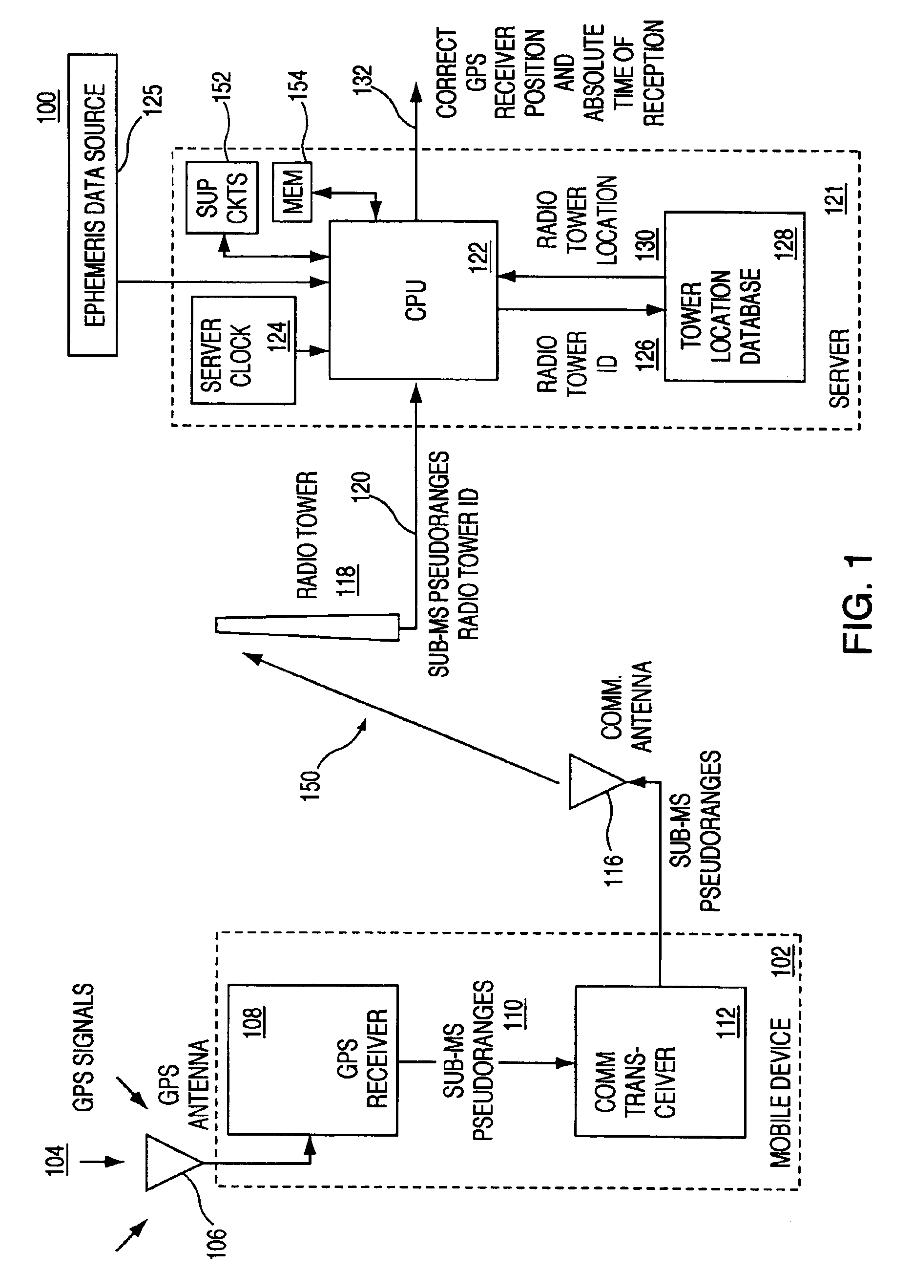
[0035]FIG. 1 depicts one embodiment of the present invention comprising an integrated mobile receiver 102 coupled to a server 121 via a wireless link 150. A GPS receiver 108 is contained in the integrated receiver 102 along with a wireless communication transceiver 112. The GPS receiver 108 measures only sub-millisecond pseudoranges with respect to GPS satellites that are in view of the receiver 108, and then sends these sub-millisecond pseudo-ranges to a server 121 using a wireless communication link...


PUM


Abstract

Method and apparatus for locating position of a satellite signal receiver is described. In one example, pseudoranges are obtained that estimate the range of a satellite signal receiver to a plurality of satellites. An absolute time and a position are computed using the pseudoranges at a first time. The absolute time is then used to compute another position at a subsequent time. In another example, a plurality of states associated with a satellite signal receiver are estimated, where the plurality of states includes a time tag error state. A dynamic model is then formed relating the plurality of states, the dynamic model operative to compute position of the satellite signal receiver.

Description

CROSS-REFERENCE TO RELATED APPLICATIONS[0001]This application is a continuation-in-part of U.S. patent application Ser. No. 10 / 190,745, filed Jul. 8, 2002 now U.S. Pat. No. 6,734,821, which is a continuation-in-part of U.S. patent application Ser. No. 09 / 715,860, filed Nov. 17, 2000 now U.S. Pat. No. 6,417,801, issued Jul. 9, 2002, each of which are incorporated by reference herein in their entireties.BACKGROUND OF THE INVENTION[0002]1. Field of the Invention[0003]The invention relates to satellite-based position location and, more particularly, the invention relates to a method and apparatus for time-free processing of global positioning system (GPS) signals.[0004]2. Description of the Related Art[0005]Global Positioning System (GPS) receivers normally determine their position by computing time delays between transmission and reception of signals transmitted from satellites and received by the receiver on or near the surface of the earth. The time delays multiplied by the speed of ...

Claims


Application Information

Patent Timeline
Patent Type & Authority Patents(United States)
IPC IPC(8): G01S5/00G01S5/14G01S1/00G01S19/23G01S19/09G01S19/11G01S19/24G01S19/25G01S19/26G01S19/27G01S19/42
CPCG01S5/0018G01S5/0036G01S19/09G01S19/235G01S19/42G01S19/27G01S19/01G01S19/11G01S19/258G01S2205/008G01S5/14
Inventor VAN DIGGELEN, FRANKABRAHAM, CHARLES
Owner BROADCOM CORP
Why Eureka
Try Eureka