
Patsnap Eureka
For R&D, Patsnap Eureka makes reading and utilizing patents & technical documents easy.
Patsnap Eureka AIR
Designed for self-driven R&D workflows. Generate viable solutions, solve complex R&D challenges, empower your innovation with AI.

Patsnap Eureka Materials
Designed for material experts only. Revolutionize your material R&D, from search, analyze, to developing new materials.

TechResearch
Generate reliable direction feasibility study reports for your R&D in just a few steps.

TechSeek
Discover and master advanced knowledge NOW. Basics, ideas, possibilities, all at once.

TechMind
As an expert in R&D Theories, TechMind can generates customized viable solutions instantly.

TechRisk
Analyze your overall solution with one click, know your potential R&D risks in advance.

TechMonitor
Get weekly tech updates, stay abreast of the latest tech innovations and key insights.
Method of making instrument panel for vehicles
a technology for instruments and vehicles, applied in the field of instruments, can solve the problems of difficult to cope with the production of small quantities of a variety of instrument panel 4 types, and achieve the effects of less viscosity, easy permeation, and increased ink reception layer
- Summary
- Abstract
- Description
- Claims
- Application Information
AI Technical Summary
Benefits of technology
Problems solved by technology
Method used
Image


Examples
first embodiment
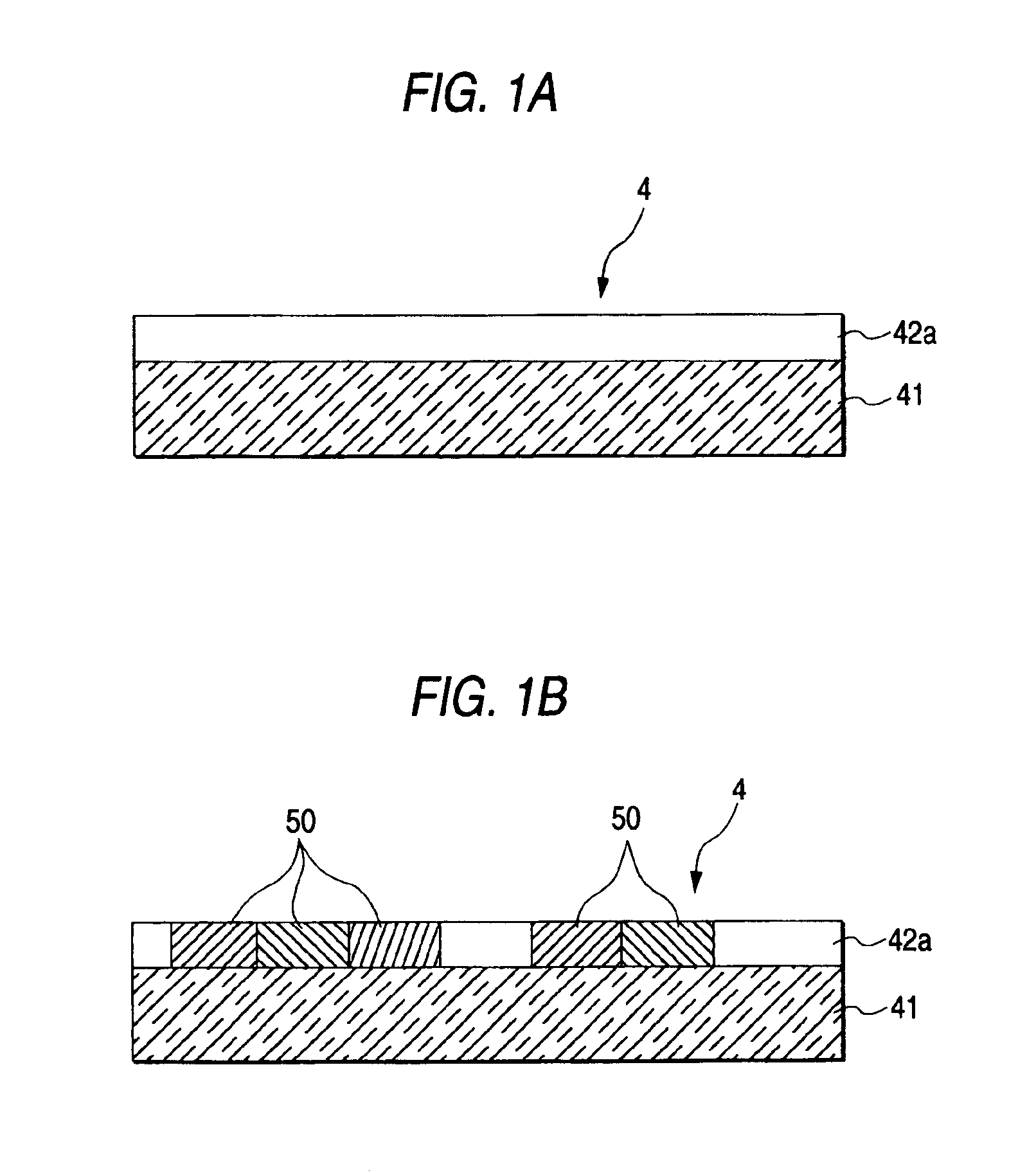
[0035]the invention will now be described while referring to FIGS. 1A and 1B.
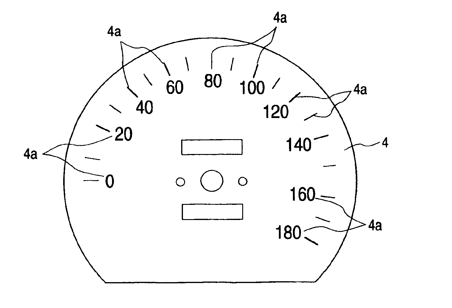
[0036]As is shown in FIG. 1A, a vehicle instrument panel (hereinafter referred to simply as an instrument panel) has a transparent substrate 41. A polycarbonate (resin), acryl or a plastic material can be employed for the substrate 41, which in this embodiment has a thickness of is 0.3 to 10 mm. When it is adopted a meter in which the instrument panel 4 is illuminated from a front side thereof, a non-transparent material can also be employed for the substrate 41.
[0037]An ink reception layer 42a is deposited on the surface of the substrate 41 by coating it with an anchor coat material that includes 20 to 80% of at least one of an urethane resin or a polyester resin. Since the instrument panel 4 is used for a meter to be mounted in a vehicle, it is preferable that the material of the ink reception layer 42a have excellent heat resistance for temperatures of from 90 to 130 degrees, and that it be ink-permeable...
second embodiment
[0045]the present invention will now be described while referring to FIGS. 2A and 2B.
[0046]As is shown in FIG. 2A, for the instrument panel 4 a substrate 41 is formed in the same manner as in the first embodiment, and ink reception layers 42a and 42b are then deposited on the obverse and reverse surfaces of the substrate 41. As in the first embodiment, it is preferable that the ink reception layers 42a and 42b be formed of an anchor coat material that contains 20 to 80% of at least one of a urethane resin or a polyester resin, and that the ink reception layers 42a and 42b exhibit excellent heat resistance to temperatures of from 90 to 130 degrees and be ink-permeable.
[0047]Further, when a light diffusion material, such as glass beads, organic beads or inorganic particles, is contained in at least one of the ink reception layers 42a and 42b, emitted light striking the instrument panel 4 is diffused in the ink reception layer 42a or 42b. When the instrument panel 4 is employed for a m...
third embodiment
[0057]the invention will now be described while referring to FIGS. 3A to 3C.
[0058]As is shown in FIG. 3A, the basic structure of the instrument panel 4 is the same as that for the second embodiment. In the third embodiment, an adhesive layer 43 is located between a substrate 41 and an ink reception layer 42a to improve the adhesion of the ink reception layer 42a to the substrate 41. Then, so long as ink can be easily fixed to the ink reception layer 42a, a less viscous material can also be used as the layer 42a, so that the available choices for the material for the ink reception layer 42a can be increased. The adhesive layer 43 may also be located between the substrate 41 and an ink reception layer 42b.
[0059]The adhesive layer 43 is obtained by depositing a polyester resin or a vinyl butyral resin on the substrate 41. When the adhesive layer 43 has the same color providing excellent visibility as the illumination color used for the character plane 4, the visibility of the design o...
PUM
| Property | Measurement | Unit |
|---|---|---|
| thickness | aaaaa | aaaaa |
| area | aaaaa | aaaaa |
| adhesive | aaaaa | aaaaa |
Abstract
Description
Claims
Application Information
 - R&D Engineer
- R&D Manager
- IP Professional
- Industry Leading Data Capabilities
- Powerful AI technology
- Patent DNA Extraction
Browse by: Latest US Patents, China's latest patents, Technical Efficacy Thesaurus, Application Domain, Technology Topic, Popular Technical Reports.
© 2024 PatSnap. All rights reserved.Legal|Privacy policy|Modern Slavery Act Transparency Statement|Sitemap|About US| Contact US: help@patsnap.com