Controllable combustion method and device

a controllable combustion and combustion method technology, applied in the direction of combustion types, machines/engines, lighting and heating apparatus, etc., can solve the problems of high pollution, inefficiency of most internal combustion engines, and loss of a great deal of energy produced by combustion, so as to reduce and simplify the energy conversion steps, reduce the effect of high bandwidth and fast energy extraction

Inactive Publication Date: 2005-09-06
SARCOS LC
View PDF22 Cites 35 Cited by
  • Summary
  • Abstract
  • Description
  • Claims
  • Application Information

AI Technical Summary

Benefits of technology

[0011]It has been recognized that it would be advantageous to develop a high bandwidth energetically autonomous combustion device that is capable of very fast energy extraction to ensure that mechanical work is performed before significant heat losses can occur. It has further been re...

Problems solved by technology

However, conventional internal combustion engines are problematic in that they can produce a high degree of pollutants and can be very inefficient.
The inefficiency of most internal combustion engines is due to the fact that a great deal of energy produced by combustion is lost as heat, energy which would otherwise be converted in to useful work.
More efficient internal combustion engines have been developed but usually at a cost of greatly increasing the weight of the engine to minimize heat loss.
Furthermore, conventional internal combustion engines have not been successfully used independently in many applications because of their relatively slow response characteristics.
This limitation is particularly problematic in powering robotic devices and similar systems which utilize a feedback loop to perform real time adjustments in movements of the mechanical structure.
But the engine cannot reach the desired change in a very rapid fashion due to inertial forces internal to the engine and the nature of the combustion process.
Moreover, if it is attempted to operate the engine repeatedly in a rapid cycle from 0 to 7000 rpms and back to 0...

Method used


Image

  • Controllable combustion method and device
  • Controllable combustion method and device
  • Controllable combustion method and device

Examples


Embodiment Construction

[0050]Reference will now be made to the exemplary embodiments illustrated in the drawings, and specific language will be used herein to describe the same. It will nevertheless be understood that no limitation of the scope of the invention is thereby intended. Alterations and further modifications of the inventive features illustrated herein, and additional applications of the principles of the inventions as illustrated herein, which would occur to one skilled in the relevant art and having possession of this disclosure, are to be considered within the scope of the invention.

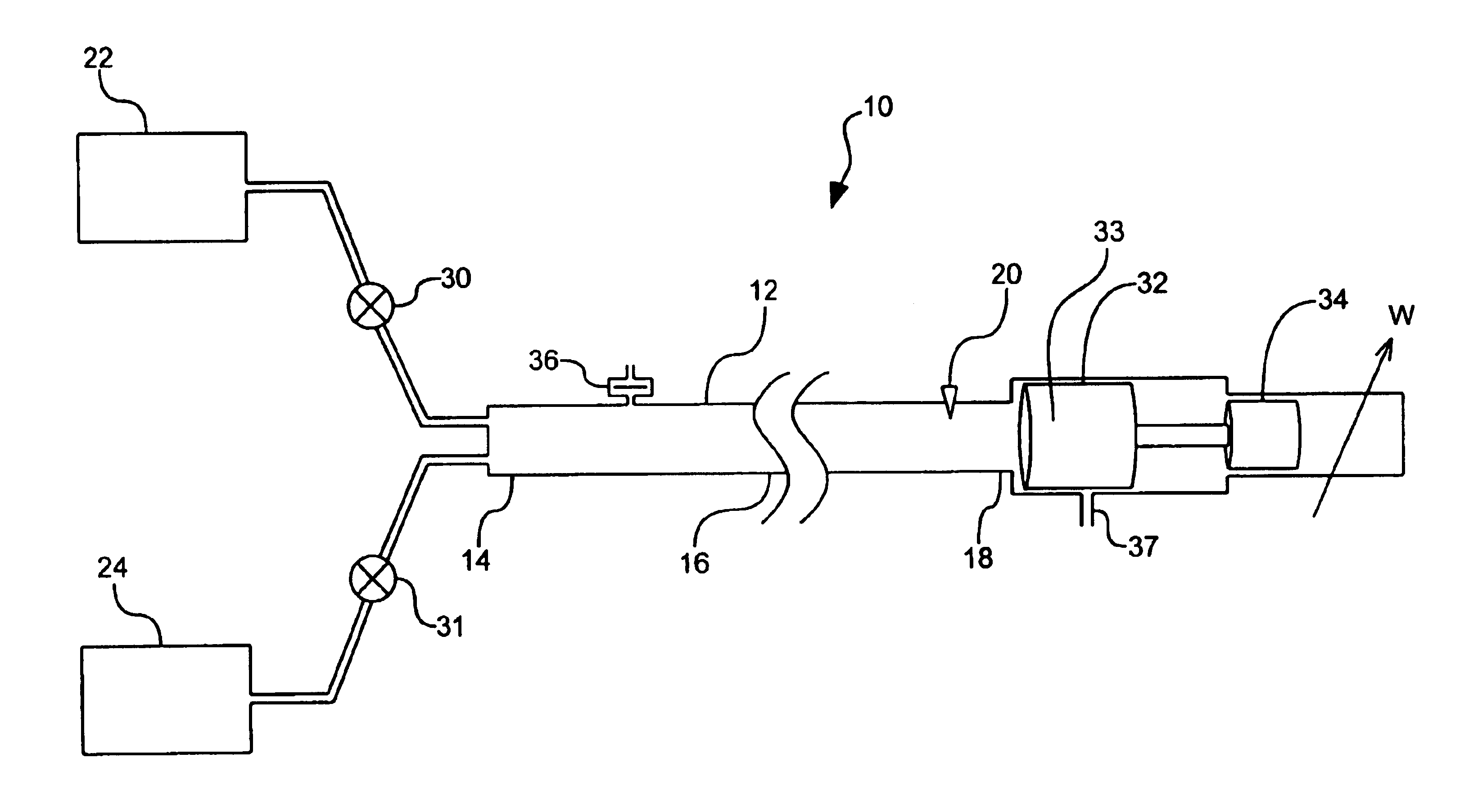
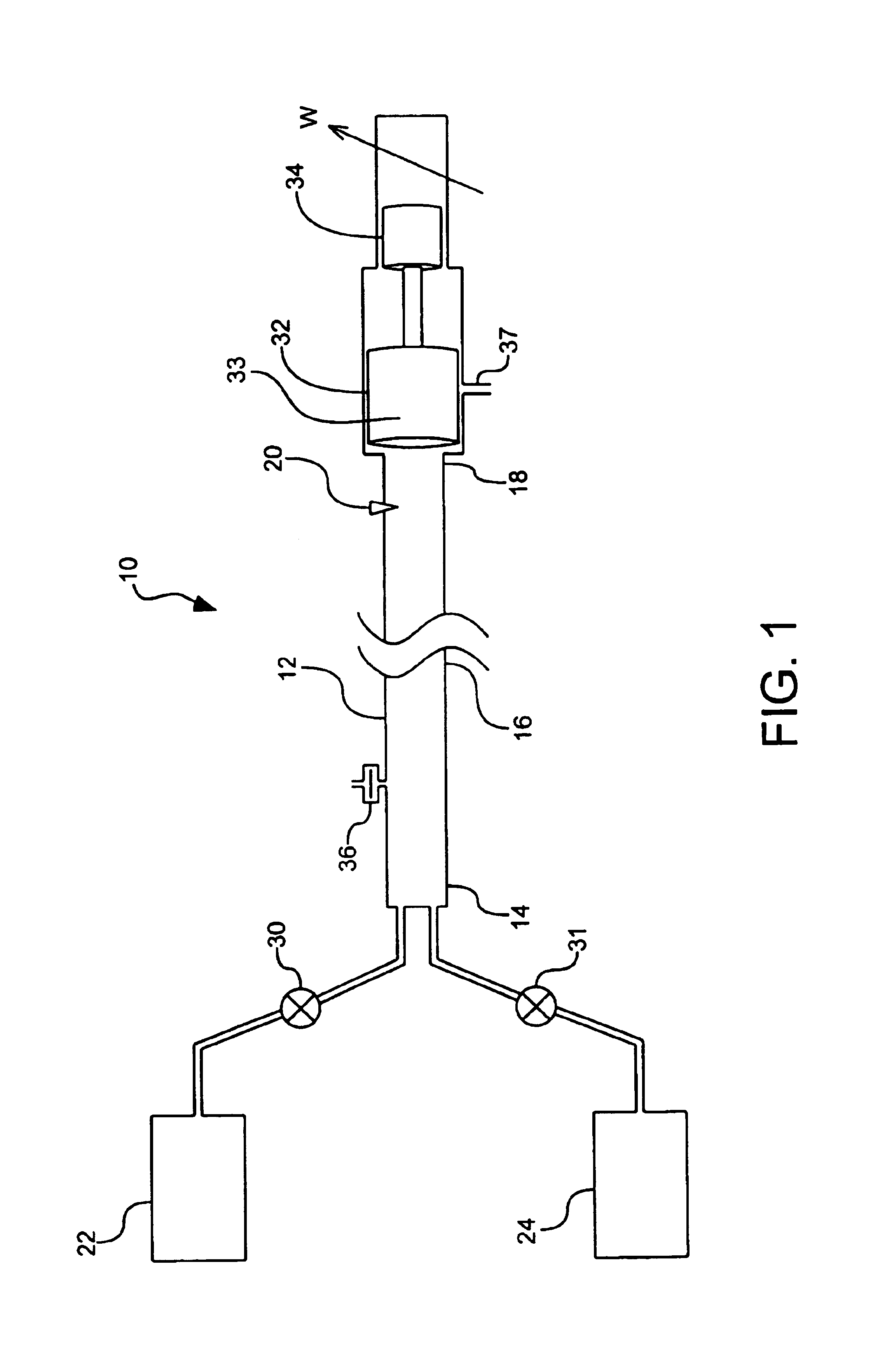
[0051]As illustrated in FIG. 1, a combustion system, indicated generally at 10, in accordance with the present invention is shown for providing controllable combustion of a combustible material. In accordance with one aspect of the present invention, the system 10 includes a combustion chamber or tube 12 that can include an extinguishing or inlet section 14, an ignition section 18, and a combustion section 16 int...


PUM


Abstract

A method and device for controllably combusting combustible material, including a combustion device comprising an elongate combustion tube having an inlet section including an inlet for combustible material, an ignition section, including an igniter displaced along a length of the tube from the inlet section to ignite the combustible material, and at least one energy extraction device operatively coupled to the combustion tube and configured to extract energy from combustion of the combustible mixture.

Description

[0001]This application is a continuation-in-part of U.S. patent application Ser. No. 09 / 439,473, filed Nov. 12, 1999 now U.S. Pat. No. 6,375,454, and claims priority to U.S. Provisional Patent Application No. 60 / 303,053, filed Jul. 5, 2001.BACKGROUND OF THE INVENTION[0002]1. Field of the Invention[0003]The present invention relates generally to a combustion device and more particularly to a lightweight, high bandwidth, controllable combustion device that can be used to power a variety of power sources.[0004]2. Related Art[0005]Power sources that directly convert combustible materials into usable energy have been used for many years in a variety of applications including motor vehicles, electric generators, hydraulic pumps, etc. Perhaps the best known example of such a power source is the internal combustion engine, which converts fossil fuel into rotational power. Internal combustion engines are used by almost all motorized vehicles and many other energetically autonomous devices su...

Claims


Application Information

Patent Timeline
IPC IPC(8): F01B11/00F02B75/28F02B75/00F23C99/00F23C6/00F02B75/02F01D1/00F02B15/00F02C6/16F02DF02D1/00
CPCF01B11/00F02B75/28F02C5/06F02K5/02F23C6/00F23C99/00F23R7/00F02B2075/025F02B2075/027F23C2900/03001
Inventor JACOBSEN, STEPHEN C.OLIVIER, MARCDAVIS, CLARK C.
Owner SARCOS LC
Why Eureka
Try Eureka