Rotary piston motor

a rotary piston and piston technology, applied in the direction of machines/engines, mechanical equipment, positive displacement liquid engines, etc., can solve the problems of lubricant pumping to the pistons, and achieve the effects of facilitating flow, facilitating flow, and improving motor efficiency, life and reliability

Inactive Publication Date: 2005-09-06
BUELNA TERRY
View PDF12 Cites 21 Cited by
  • Summary
  • Abstract
  • Description
  • Claims
  • Application Information

AI Technical Summary

Benefits of technology

[0004]By way of overview, the rotary motor disclosed herein increases motor efficiency, life and reliability by using a journal bearing on the piston to more efficiently and durably carry the transmitted forces that a roller exerts on a guide track. The motor also preferably, but optionally provides a lubricating and cooling fluid to that journal bearing, and does so through a passageway design that uses centrifugal help force to facilitate flow through the fluid passageways. Further, a centrifugally fed, lubricating fluid passageway is provided to an inner surface of the guide track to reduce wear and increase cooling of the abutting surfaces which carry the centrifugal forces of the rotating motor. Lateral seals are also provided between the annular seals at the end of each piston cylinder, to improve the sealing of the rotary portion of the motor. Advantageously two rings of lateral seals are provided, and inner and outer ring concentric about the rotational axis, and spaced apart by the annular cylinder bore seals.
[0006]Preferably, but optionally, the roller which contacts the guide track and which transfers linear piston motion into rotary motion is supported by a journal bearing. This allows a more efficient transfer of high loads while reducing wear compared to prior art rollers. Pinning or bolting or otherwise supporting the roller and journal bearing between opposing skirts of the piston allows for simple and efficient mounting of the bearing and roller.
[0008]Further, there is also preferably, but optionally, a fluid path in the journal bearing having a first end that opens onto a radial face of the bearing and an another end that opens onto the roller so the inner face of the roller acts as part of the journal bearing, with the first end being aligned with the fluid lubricating passageways through the piston. Because of the rotation of the drive shaft and the rotation of the pistons around the drive shaft, this can result in the pumping of lubricant through the pistons and to the journal bearing, and the further radial alignment of fluid passageways in the piston with the fluid passageway in the journal bearing and with the fluid passageways in the drive shaft. This provides a simple and efficient lubricating and cooling fluid to the roller.

Problems solved by technology

Because of the rotation of the drive shaft and the rotation of the pistons around the drive shaft, this can result in the pumping of lubricant to the pistons.

Method used


Image

  • Rotary piston motor
  • Rotary piston motor
  • Rotary piston motor

Examples


Embodiment Construction

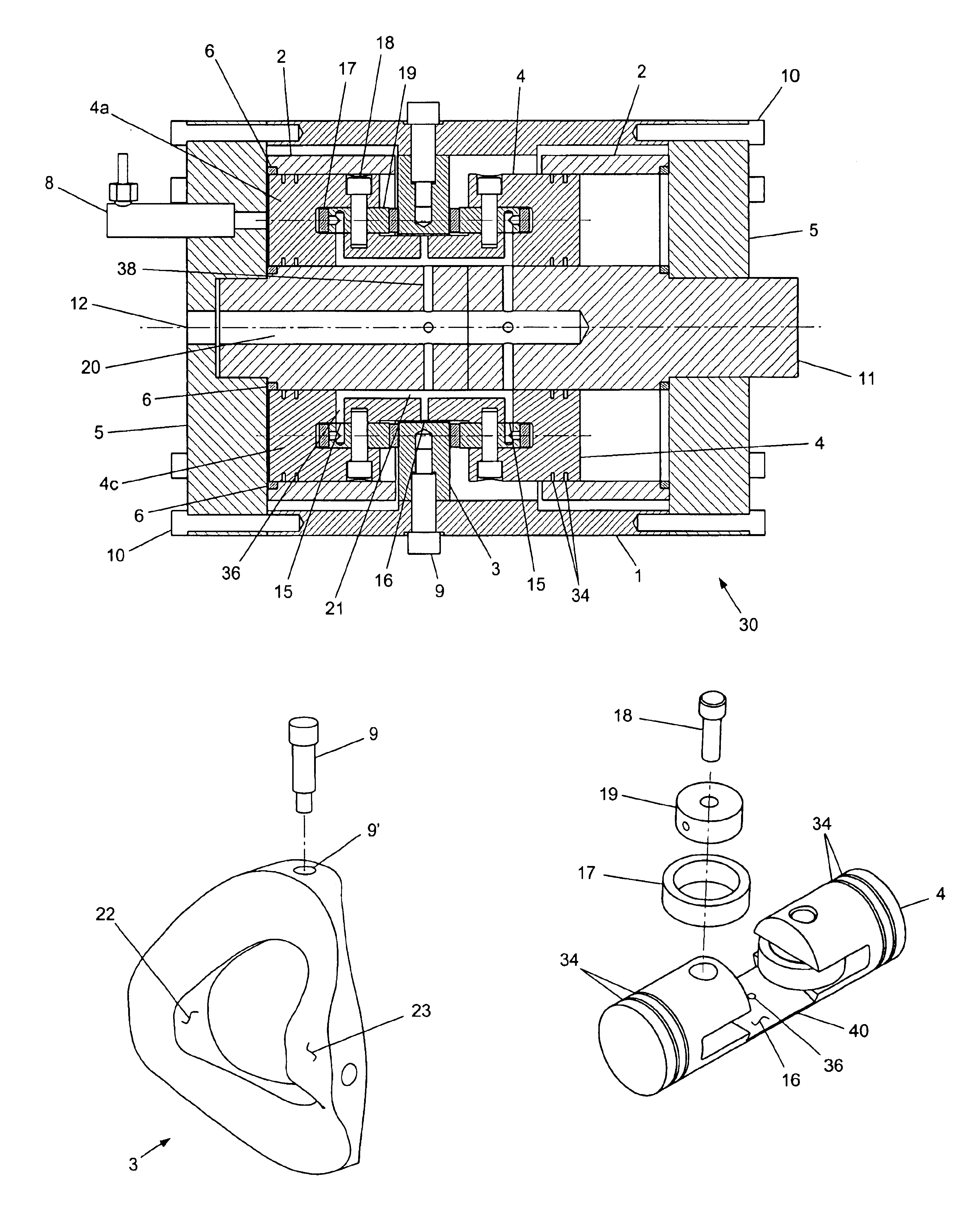
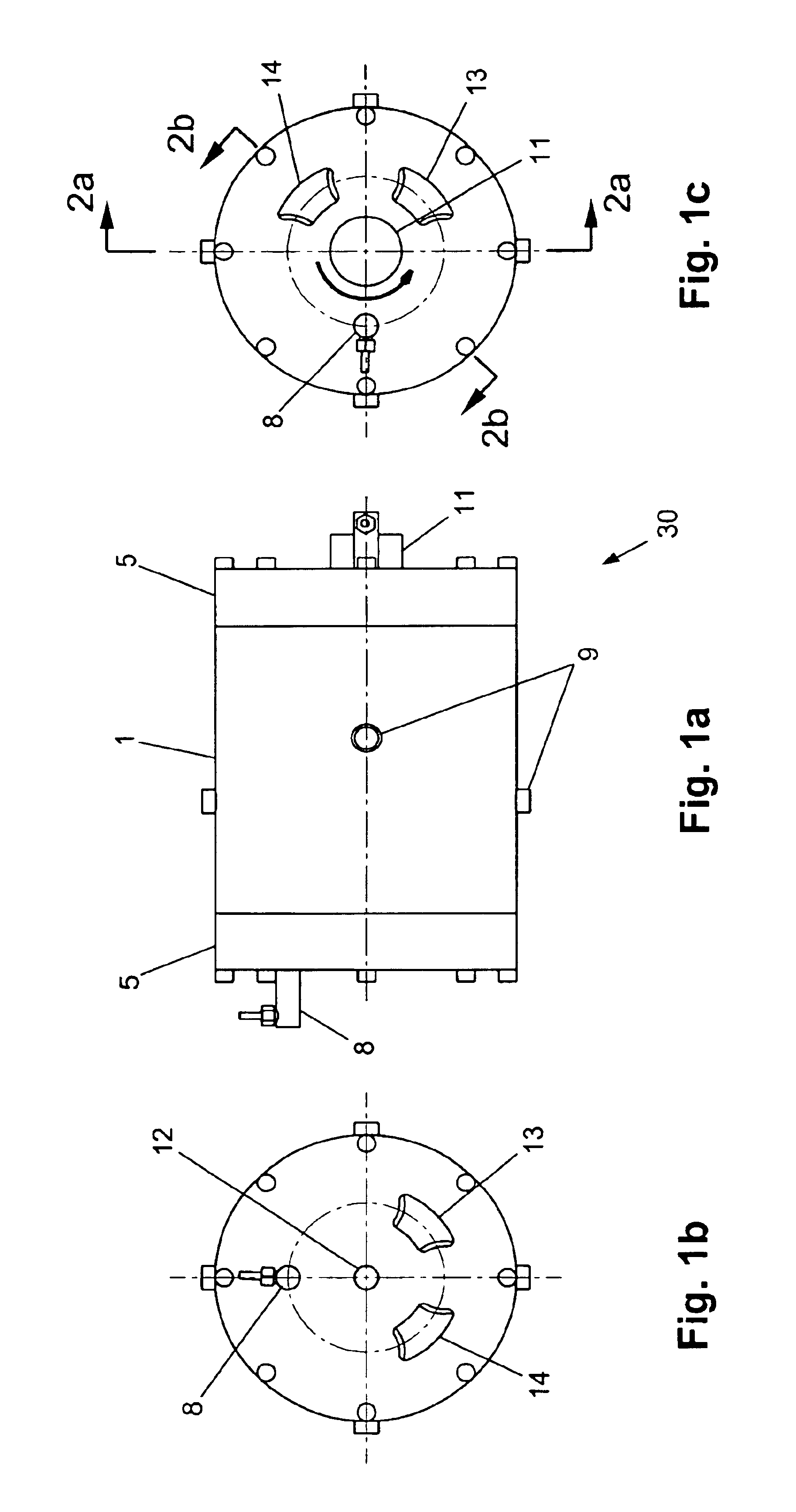
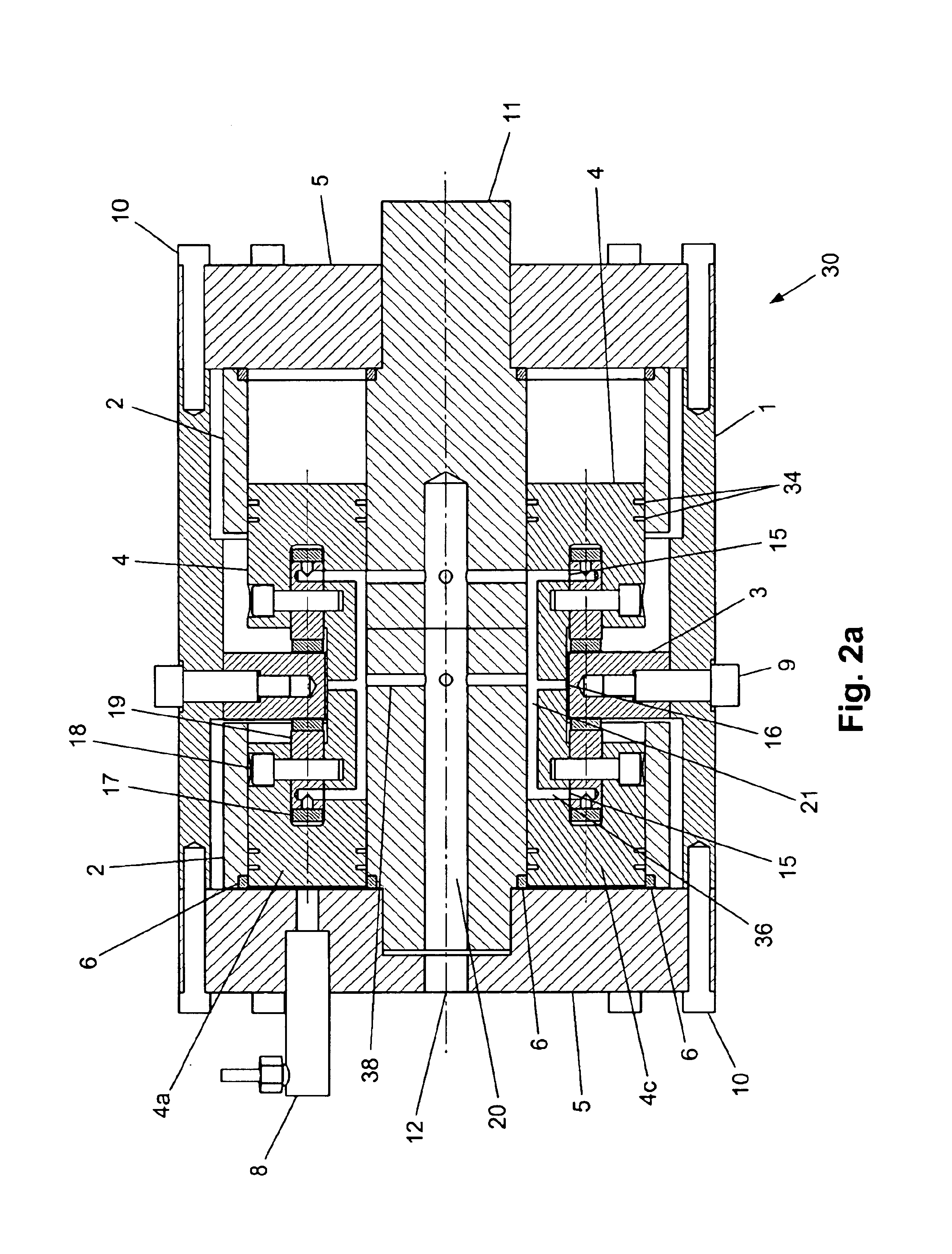
[0034]Referring to FIGS. 1-3, an internal combustion, reciprocating piston, rotary motor 30 is provided. This motor 30 can be adapted to either two-cycle or four-cycle operation. It is also adaptable for either spark-ignited or compression-ignited use. The motor 30 has one or more reciprocating pistons 4, and preferably has an even number of pistons. The engine 30 may be used in any application that a conventional reciprocating piston internal combustion engine is used. The motor 30 shown and described herein is a double-ended configuration with four pistons and four cylinders, with intake / exhaust porting for four-cycle operation. The engine configuration would be equivalent to an eight cylinder conventional reciprocating engine. But the engine 30 can be produced with any number of cylinders desired, and the cylinders can be double ended or single ended.

[0035]The engine 30 has a stationary (non-rotating) engine casing or crankcase 1 that preferably takes the form of a cylindrical, t...


PUM


Abstract

An internal combustion, reciprocating piston, motor has a rotating cylinder block. A journal bearing supports a roller that is fastened to a piston connecting rod or fastened to the piston so the roller pushes against an inclined surface on a stationary guide track fastened to a motor housing in order to cause the cylinder block and pistons to rotate. A lubricant is fed from a passageway on the rotational axis of the drive shaft radially outward, through passageways that align, and though a skirt on the piston, in order to lubricate the journal bearing. The rotating piston chambers are sealed against a stationary cylinder head by annular rings at the end of each chamber, and by curved linear seals extending between adjacent annular rings.

Description

CROSS-REFERENCE TO RELATED APPLICATIONS[0001]This application claims priority under 35 U.S.C. §119 (e) to provisional patent application No. 60 / 463,048, filed Apr. 16, 2003, Terry Buelna inventor.BACKGROUND OF THE INVENTION[0002]This invention involves a rotary piston motor having pistons that reciprocate parallel to a central drive shaft while the pistons also rotate around that drive shaft with the engine casing remaining stationary.[0003]Such rotary motors have been previously designed for envisioned use as motors to rotate a shaft, or conversely to pump fluid from the piston cylinders if power is supplied to rotate the shaft. But prior rotary motors have not been commercially viable products, in part because of unacceptable wear, reliability and performance, and in part because of the engine complexity. There is thus a need for a rotary piston motor that is simpler yet more reliable.BRIEF SUMMARY OF THE INVENTION[0004]By way of overview, the rotary motor disclosed herein increas...

Claims


Application Information

Patent Timeline
Patent Type & Authority Patents(United States)
IPC IPC(8): F02B75/26F02B75/00F04B1/20F04B15/08F04B15/00
CPCF02B75/26F04B1/2028F04B15/08
Inventor BUELNA, TERRY
Owner BUELNA TERRY
Why Eureka
Try Eureka