Corrugated fin

Inactive Publication Date: 2005-09-06
CALSONIC KANSEI CORP
View PDF12 Cites 11 Cited by
  • Summary
  • Abstract
  • Description
  • Claims
  • Application Information

AI Technical Summary

Benefits of technology

[0022]During the manufacturing method of the corrugated fin, when two types of corrugated fin portions having different fin widths are corrugated to form the corrugated fin, a bend of the corrugated fin is corrected by widening to the predetermined width the wave pitch inside th

Problems solved by technology

However, the conventional corrugated fin has such a problem in that, when the fin widths of the corrugated fin integrally formed with the corrugated fin of the composite heat exchanger are made different from each other,

Method used


Image

  • Corrugated fin
  • Corrugated fin
  • Corrugated fin

Examples


first embodiment

[0030]First, a structure will be explained.

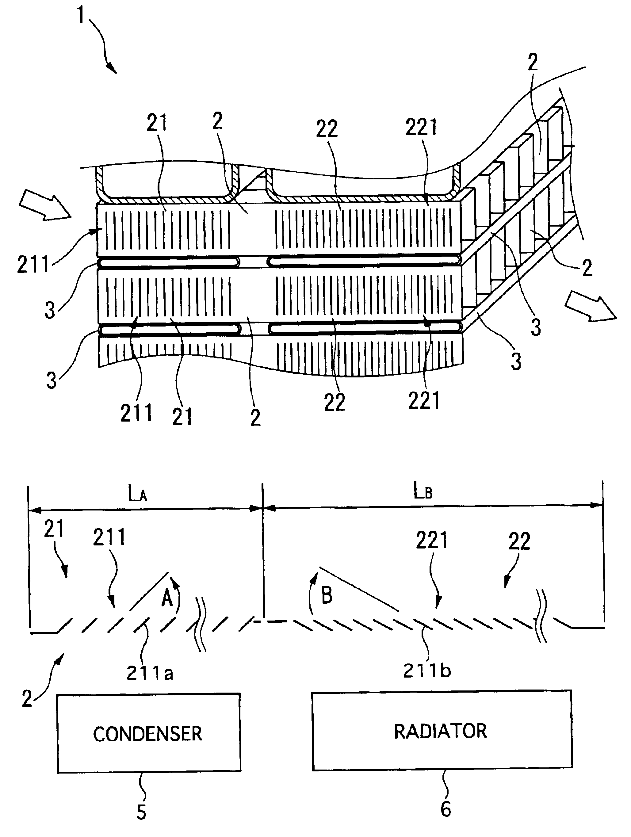
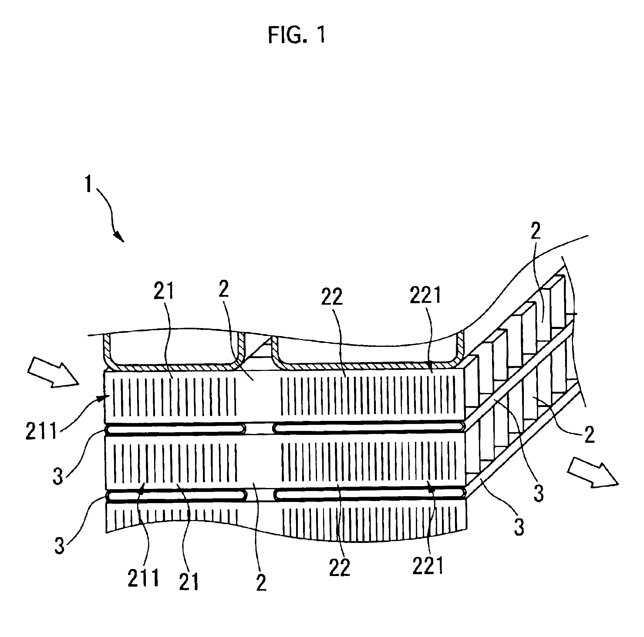
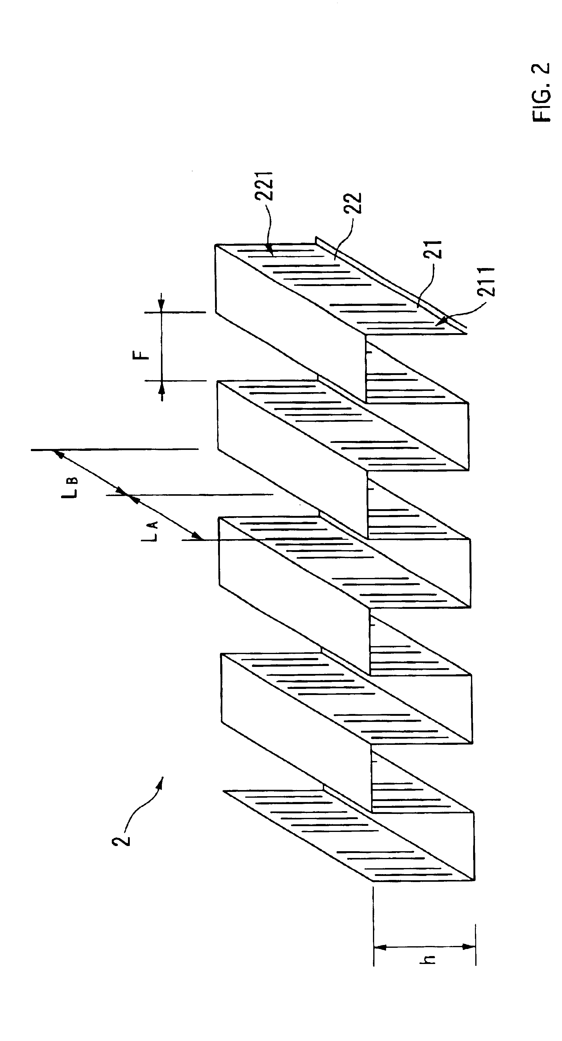
[0031]FIG. 1 is an explanatory view showing a part of a composite heat exchanger using a corrugated fin of a first embodiment. FIG. 2 is an enlarged view of the corrugated fin of the first embodiment. FIG. 3 is a schematic view showing a cross-section of the corrugated fin of the first embodiment.

[0032]As shown in FIG. 1 to FIG. 3, a composite heat exchanger 1 includes plural corrugated fins 2 respectively having a condenser portion 21 and a radiator portion 22, and tubes 3 arranged between these corrugated fins 2.

[0033]The first embodiment is an example of the corrugated fins 2 which are used for the composite heat exchanger 1, which comprises a condenser 5 and a radiator 6 arranged in a parallel relationship with each other and mounted in a motor vehicle.

[0034]Each corrugated fin 2 is, as shown in FIG. 2, integrally formed of the condenser portion 21, corresponding to a first corrugated fin portion of the present invention and used as a c...

second embodiment

[0050]In a second embodiment, as shown in FIG. 5, a condenser portion 21 corresponding to a first corrugated fin portion of the present invention has a fin width PA smaller than a fin width PB of a radiator portion 22 corresponding to a second corrugated fin portion of the present invention. The condenser portion 21 and the radiator portion 22 have first and second louvers 21 and 22, respectively. The first and second louvers 21 and 22 are formed with first and second louver slats 211a and 22 la, respectively. A pitch PB of the second louver slats 221a of the second louver 221 of the radiator portion 22 is smaller than a pitch PA of first louver slats 211a of the first louver 21 of the condenser portion 21.

[0051]Incidentally, other structure is the same as that of the corrugated fins 2 of the first embodiment, so an explanation thereof is omitted.

[0052]Here, prevention of bending of the corrugated fins 2 during formation of the corrugated fin 2 is, if necessary performed as follows....


PUM

PropertyMeasurementUnit
Angleaaaaaaaaaa
Speedaaaaaaaaaa
Widthaaaaaaaaaa

Abstract

A corrugated fin for a composite heat exchanger for motor vehicles includes a condenser portion and a radiator portion. The radiator portion is larger in fin width than the condenser portion. The condenser portion and the radiator portion respectively have first and second louvers formed corresponding to the fin widths. The first and second louvers respectively have first and second louver slats inclined in a direction which is different for each of the condenser portion and the radiator portion so as to oppose each other, and an inclination angle of the second louver slats is smaller than an inclination angle of the first louver slats.

Description

BACKGROUND OF THE INVENTION[0001]1. Field of the Invention[0002]The present invention belongs to a technical field of a corrugated fin for composite heat exchangers.[0003]2. Description of the Related Art[0004]A conventional corrugated fin corresponds to required heat release amounts of respective heat exchangers by making a fin width and a number of louver slats different between a condenser side and a radiator side. (For example, refer to Japanese Patent Laid-open No. Hei 10-253276.)[0005]Regarding composite heat exchangers used particularly for motor vehicles, there has been a demand to make thicknesses of a condenser and a radiator, which compose a composite heat exchanger, different according to diversification of size of cabin and diversification of required specification of cooling performance in an engine room. In this case, a corrugated fin should be made to have a different fin width between the condenser side and the radiator side. However, the conventional corrugated fin...

Claims


Application Information

Patent Timeline
IPC IPC(8): F28F1/12F28D1/04B60H1/32F01P3/18F01P3/22F28F1/30
CPCF28D1/0408F28F1/128Y10T29/4935F28F2215/02
Inventor IWASAKI, MITSURU
Owner CALSONIC KANSEI CORP
Why Eureka
Try Eureka