Device for sensing parameters of a hollow body organ

a technology of hollow body organs and sensors, applied in the field of invasive medical devices, can solve the problems of inability to determine whether the inflamed plaque is inflamed, unstable type, and unstable type, and achieve the effect of maintaining sterility and increasing the sampling resolution

a technology of hollow body organs and sensors, applied in the field of invasive medical devices, can solve the problems of inability to determine whether the inflamed plaque is inflamed, unstable type, and unstable type, and achieve the effect of maintaining sterility and increasing the sampling resolution

US6939313B2Inactive Publication Date: 2005-09-06SAADAT VAHID

Image

  • Device for sensing parameters of a hollow body organ
  • Device for sensing parameters of a hollow body organ
  • Device for sensing parameters of a hollow body organ

Examples


Embodiment Construction

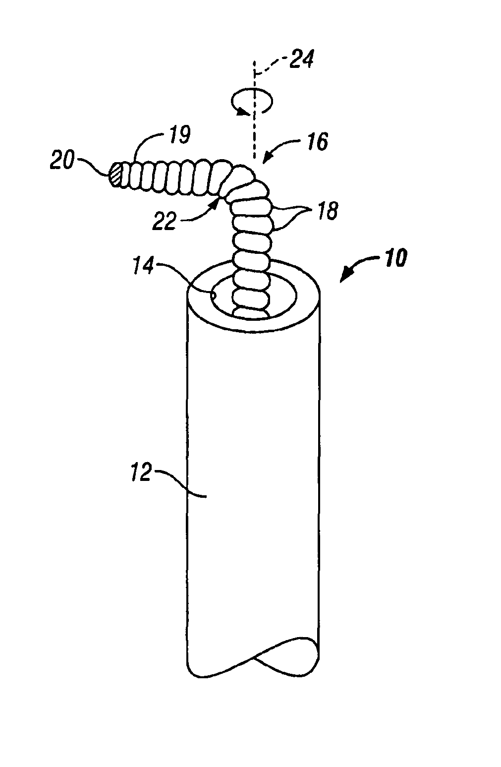
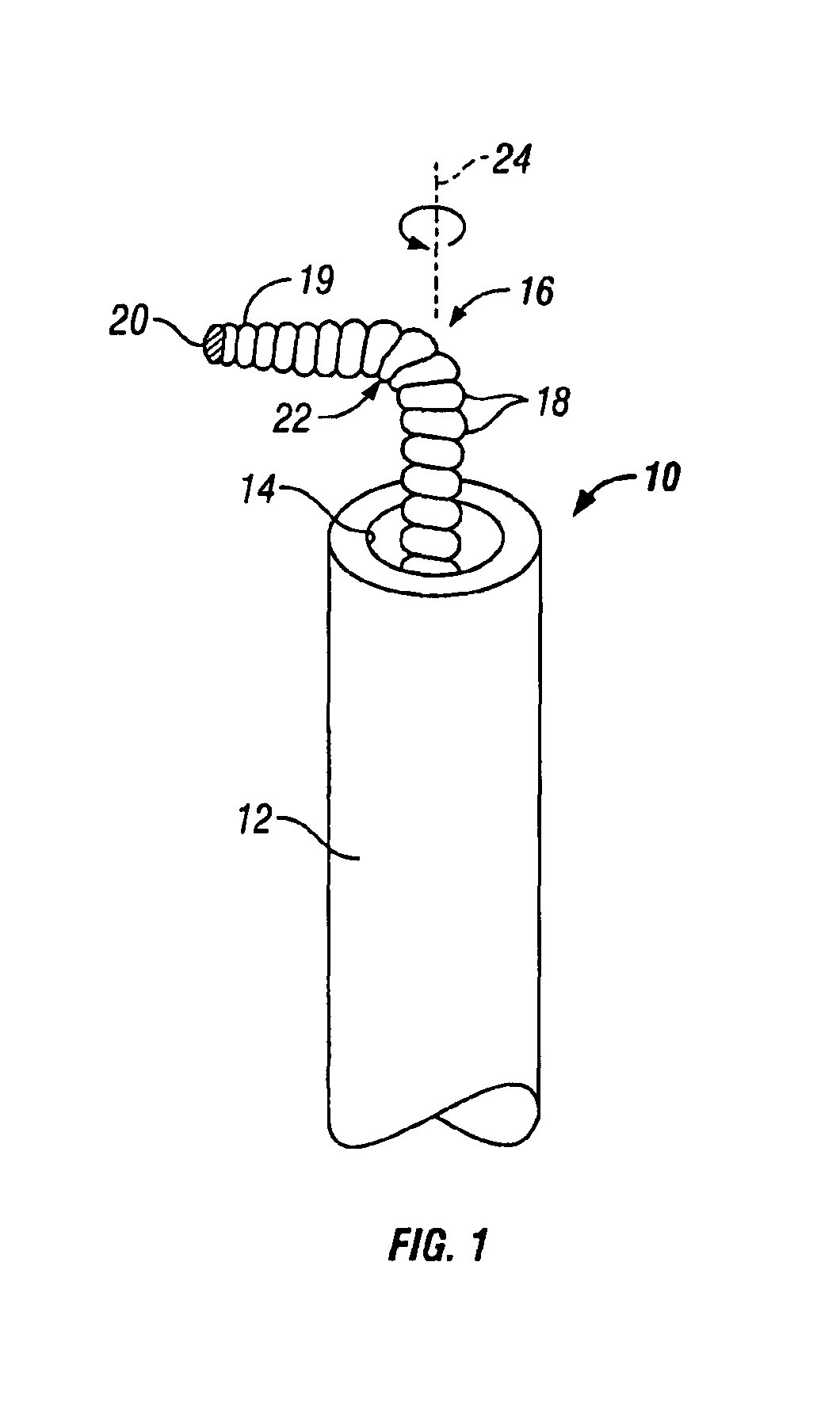
[0058]FIG. 1 shows a device 10 for profiling the wall of a hollow body organ. Device 10 includes a lumened catheter 12 having a central lumen 14, a hollow guidewire 16 that defines a conduit comprising a metal wire 18 or the like in the shape of a coil defining a central lumen (not shown), and a thermal sensor 20 disposed at the terminal end of the distal portion of guidewire 16. Conventional conductors or other signal carrying structures (not shown) are provided to convey signals from the thermal sensor 20 along guidewire 16 and out of the proximal portion of guidewire 16 for connection to appropriate signal processing apparatus that converts the signals to a temperature indication. Thermal sensor 20 can be, e.g., a thermocouple, a thermistor, an infrared radiation sensor, fiberoptic oxygen sensor, ultrasonic transducer, impedance sensor, pH sensor, mechanical force sensor (e.g., strain gauge), etc., for example, and is secured by appropriate mechanical or adhesive means to the ter...


PUM


Abstract

A device for sensing the profile of a hollow body organ includes a hollow guidewire or probe carrying a sensor. The hollow probe includes a distal coiled end tube with a tip bent at an angle between about 10° to 90° relative to the probe longitudinal axis and having a torque response of no more than about 0.4 ozf in. The flexural rigidity of the distal end tube relative to the mid and proximal end tubes forming the probe is generally in the range of about 1:(4 to 4,400):(110 to 13,000), respectively. An actuator is detachably secured to the probe and includes one or several motors which allow the sensor to travel in a rotational and axial path through the body organ.

Description

CROSS-REFERENCE TO RELATED APPLICATIONS[0001]This application is a continuation-in-part of U.S. patent application Ser. No. 09 / 904,212, filed on Jul. 12, 2001 (now abandoned).TECHNICAL FIELD OF THE INVENTION[0002]This invention relates generally to invasive medical devices and more particularly to devices for sensing the profile of the interior wall of a hollow body organ such as a blood vessel.BACKGROUND OF THE INVENTION[0003]Acute ischemic syndromes involving arterial blood vessels, such as myocardial infarction, or heart attack, and stroke, frequently occur when atherosclerotic plaque ruptures, triggering the formation of blood clots, or thrombosis. Plaque that is inflamed is particularly unstable and vulnerable to disruption, with potentially devastating consequences. Therefore, there is a strong need to detect and locate this type of plaque so that treatment can be initiated before the plaque undergoes disruption and induces subsequent life-threatening clotting.[0004]Various pr...

Claims


Application Information

Patent Timeline
06 Sep 2005
Publication
US6939313B2
IPC
A61B5/00; A61B5/01; A61B5/103; A61B5/107; A61B5/117
CPC
A61B5/015; A61B5/0538; A61B5/1076; A61B5/1077; A61M2025/09116
Inventors
SAADAT, VAHID; TSUGITA, ROSS