
Broadband dipole antenna to be worn by a user and associated methods

a dipole antenna and user technology, applied in the field of communication, can solve the problems of unwieldy user, poor performance, and large antenna, and achieve the effect of good performan

Inactive Publication Date: 2005-09-06
NORTH SOUTH HLDG
View PDF20 Cites 14 Cited by
  • Summary
  • Abstract
  • Description
  • Claims
  • Application Information

AI Technical Summary

Benefits of technology

"The present invention provides an antenna that can be worn by a user and provide good performance over a wide frequency band. The antenna includes a dipole feed, a first dipole element, a transmission line, and a flexible electrically conductive sleeve. The sleeve can serve as a second dipole element and as a balun. The dipole feed includes a broadband matching network, and the antenna includes a noise filter adjacent the transmission line. The flexible electrically conductive sleeve can be bent at a right angle to the user's body, and the first dipole element is biased back to the straight position. The antenna can be removably fastened to the user's garment with a fastener. The method of making the antenna involves coupling the dipole element and transmission line, and then adding the flexible electrically conductive sleeve and noise filter. The technical effects of this invention include improved broadband performance, compact and robust design, and enhanced user experience."

Problems solved by technology

Such a large antenna may simply be too unwieldy for many applications.
In other similar portable radios, a short flexible rubber duck antenna may be used, however, performance may not be as good as with the blade antenna.
A long whip antenna may provide better performance, but may be unwieldy for the user.
Unfortunately, all these antenna types require a counterpoise provided by the radio itself.
In addition, electromagnetic noise from interferers may limit sensitivity of the receiver of the radio.
Unfortunately, such an antenna may not be suitable for longer range communications.
Such an antenna may be not meet the durability requirements to be worn by a user or have sufficient power handling capability for longer range communication.

Method used


Image

  • Broadband dipole antenna to be worn by a user and associated methods
  • Broadband dipole antenna to be worn by a user and associated methods
  • Broadband dipole antenna to be worn by a user and associated methods

Examples


Embodiment Construction

[0020]The present invention will now be described more fully hereinafter with reference to the accompanying drawings in which preferred embodiments of the invention are shown. This invention may, however, be embodied in many different forms and should not be construed as limited to the illustrated embodiments set forth herein. Rather, these embodiments are provided so that this disclosure will be thorough and complete, and will fully convey the scope of the invention to those skilled in the art. Like numbers refer to like elements throughout, and prime notation is used to indicate similar elements in alternate embodiments.

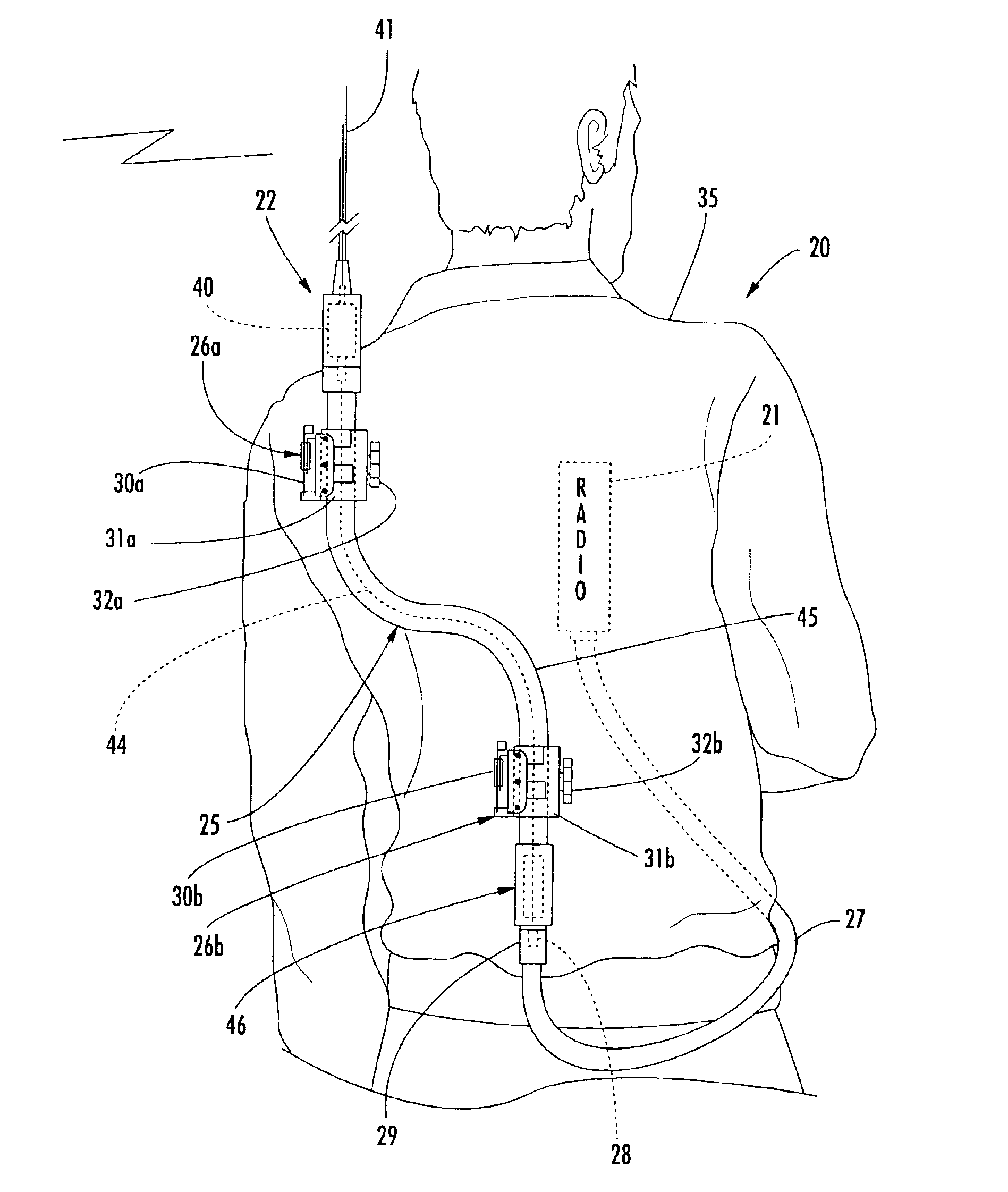
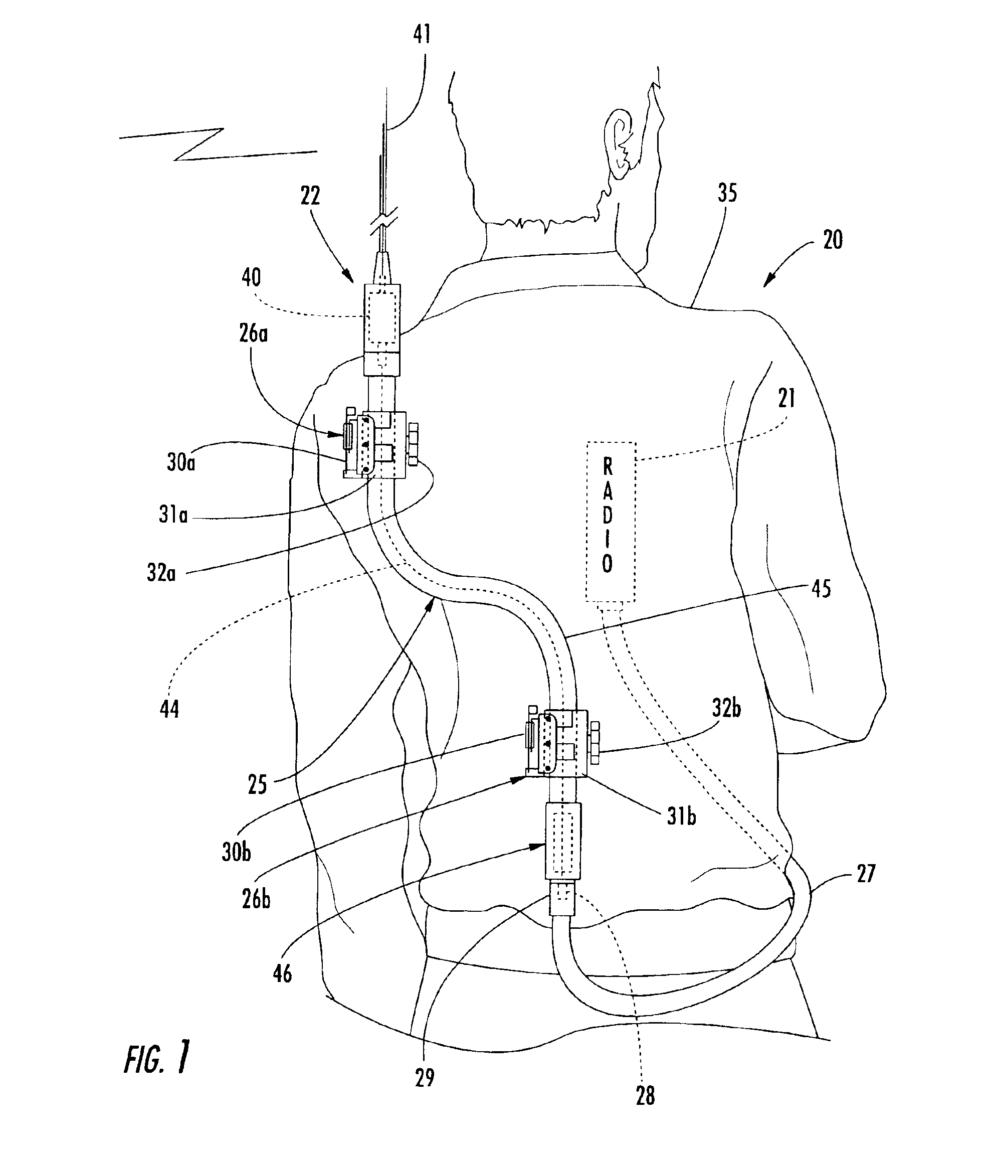
[0021]Referring initially to FIG. 1, the components of a portable communications system 20 in accordance with the invention are now described. The system 20 includes a radio 21, and an antenna assembly 22 connected to the radio. The radio 21 may be a portable unit, such as the model RF-5800V-HH that is a small, lightweight VHF handheld radio offered by Harris RF Co...


PUM


Abstract

An antenna includes a dipole feed, a first dipole element connected to and extending outwardly from the dipole feed, a transmission line extending from the dipole feed in an opposite direction, and a flexible electrically conductive sleeve surrounding the transmission line and connected to and extending outwardly from the dipole feed. The electrically conductive sleeve may thus serve as a second dipole element and as a balun for the antenna. The antenna may by removably fastened to a garment of the user by at least one fastener, and the antenna may be connected to a radio also carried by the user. To enhance broadband performance, the dipole feed may include a broadband matching network, and the antenna may include a noise filter coupled to the transmission line adjacent an end of the flexible electrically conductive sleeve opposite the dipole feed.

Description

FIELD OF THE INVENTION[0001]The present invention relates to the field of communications, and, more particularly, to an antenna that may be worn by a user.BACKGROUND OF THE INVENTION[0002]Portable radio communications are widely used to enable coordination between spaced apart users, such as policemen, fireman, or military personnel, for example. U.S. Pat. No. 2,576,128 to Lense issued Nov. 27, 1951 discloses an early version of a manpack antenna, such as for a soldier, that is in the form of a dipole including upper and lower dipole elements. These elements are centrally fed adjacent the waist of the user and extend upwardly toward the user's shoulder and downwardly to the user's knee. Such a large antenna may simply be too unwieldy for many applications.[0003]A more advanced type of portable radio is known as the mini-manpack radio, such as the RF-5800V-HH VHF radio offered by Harris RF Communications Division of Rochester, N.Y. The five watt output mini-manpack handheld radio may...

Claims


Application Information

Patent Timeline
Patent Type & Authority Patents(United States)
IPC IPC(8): H01Q1/10H01Q9/04H01Q1/08H01Q1/27H01Q9/16H04B1/38
CPCH01Q1/084H01Q1/085H01Q1/10H01Q1/273H01Q9/16H04B1/385
Inventor PACKER, MALCOLM J.
Owner NORTH SOUTH HLDG
Learn More