
Robotic system

a robot and system technology, applied in the field of robot systems, can solve the problems of damage to the surface, and inability to meet the needs of users, and achieve the effect of avoiding or minimising over-application

Inactive Publication Date: 2005-09-06
THE PROCTER & GAMBLE COMPANY
View PDF53 Cites 216 Cited by
  • Summary
  • Abstract
  • Description
  • Claims
  • Application Information

AI Technical Summary

Benefits of technology

[0012]By detecting the application of the fluent material, which may be a liquid or gaseous fluid or else a flowable powder, the over-application of material can be avoided or minimised by either navigating the robot around areas already treated and / or by controlling the depositing mechanism to stop the deposit of material over such previously treated areas.
[0018]Utilising a generally circular shape together with a control regime which scans for the best direction of escape after the robot has become stuck (say in a corner) is especially advantageous. Furthermore, it may be additionally advantageous to detect the angle of any collision, in order to optimise the robots subsequent angle of movement away from the obstacle.
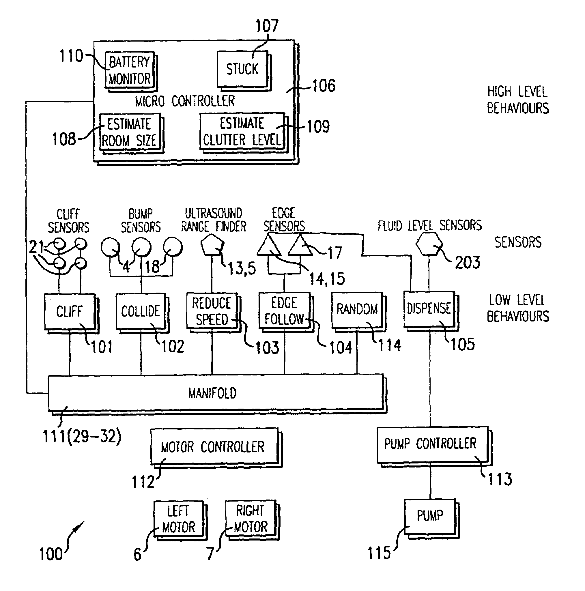
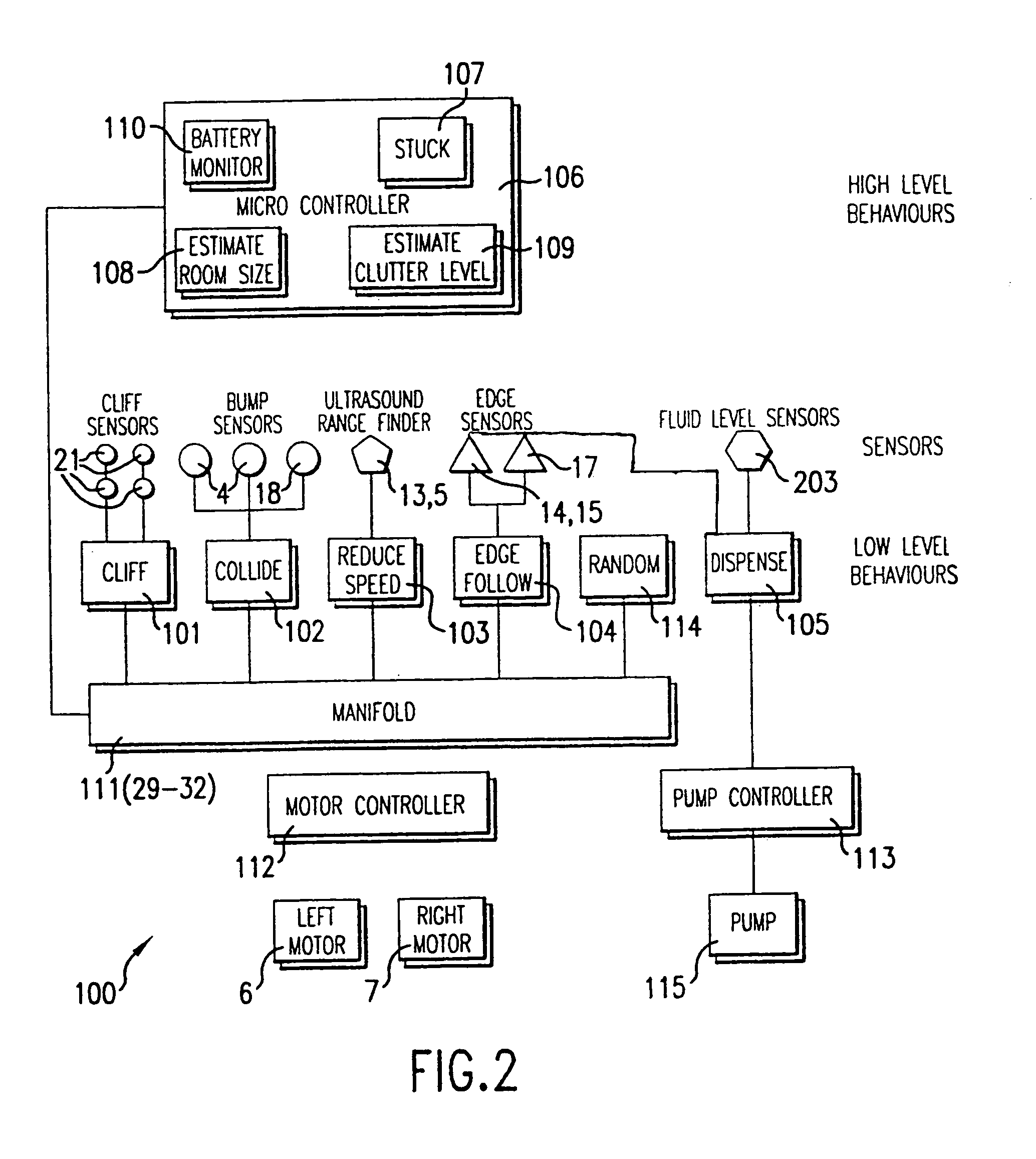
[0022]The robot further preferably comprises a control system for controlling deposition of the material dependent on the signals received from the one or more detectors and sensors. In preferred embodiments, the control system functions to control deposition of the material (e.g. to avoid or minimise over-application) by a combination of strategies comprising a)navigating the robot around previously-treated areas of the surface (referred to herein as the ‘navigation strategy’; and b) controlling the depositing mechanism to stop or reduce the deposit of fluent material on to the surface as the robot passes over such previously-treated areas (referred to herein as the ‘deposition rate control strategy’). In practice, the control system arbitrates between the two strategies depending on the signals received from the navigation sensors and deposition detectors. The ability of the control system to arbitrate between the two strategies, for example to make a rapid judgment on whether to cross or navigate around previously-treated areas and whether to maintain, reduce or stop deposition accordingly, is an important feature for ensuring controlled deposition in the context of a fully autonomous robot designed to operate in the cluttered, unstructured and track-free environment typically found in domestic and institutional situations.
[0023]Alternatively, the control system can be designed to control deposition purely following a deposition rate control strategy, in other words, by controlling the depositing mechanism to stop or reduce the deposit of fluent material on to the surface as the robot passes over previously-treated areas. Of course, systems depending purely on deposition rate control require less complicated electronics than the preferred combined-strategy systems described above. On the other hand, single strategy systems can be less efficient in terms of the time required to complete the task in hand.

Problems solved by technology

Unfortunately, on-board processing power is inevitably limited by cost constraints in particular and therefore present systems, to avoid be prohibitively expensive, have relatively limiting navigational abilities which result, in use, in the robot tracing a path which involves passing over the same areas of the surface on plural occasions.
Whilst this may not be problematic in say a vacuum cleaner, if the robot has the function of treating the surface in other ways, then such redundant movement may result in over-treatment of the surface which is not only wasteful of the product used for the treatment (a serious problem where the payload is restricted), but may also damage the surface or otherwise actually be harmful.

Method used


Image

  • Robotic system
  • Robotic system
  • Robotic system

Examples


Embodiment Construction

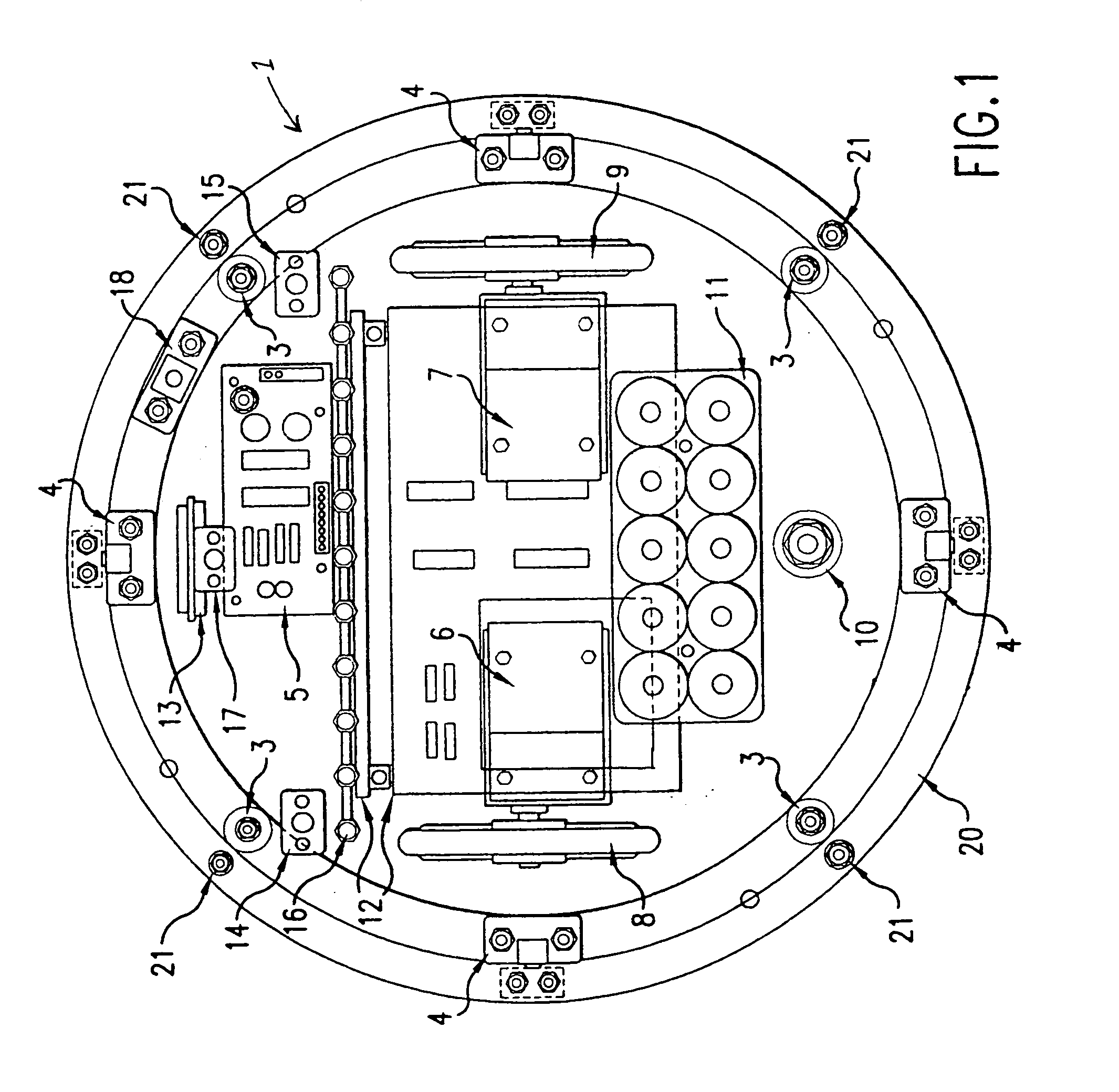
[0029]As can be seen from FIG. 1, the robot of the present example is substantially circular in overall plan view. A simple plate-like chassis 1 supports both the mechanical and electrical components of the robot. The plate-like chassis 1 supports the body (not shown) of the robot on resilient rubber mountings 3 which allow the body to move relative to the chassis 1 when a force is applied, e.g. by collision with an object, to a sensor ring 20 which is disposed around the periphery of the body. Four displacement sensors 4 placed at 90° intervals around the robot measure lateral displacement of the body relative to the chassis 1 and inform the control system of contact with an external object. The displacement sensors 4 are based on linear Hall Effect devices which produce a voltage which is proportional to the strength of the magnetic field in which they are immersed. Each sensor consists of a small permanent magnet mounted on the body shell support ring 20 and a Hall Effect device ...


PUM


Abstract

A self-propelled robot is disclosed for movement over a surface to be treated. The robot has a power supply and a pair of wheels driven by motors for moving the robot over the surface. A mechanism is provided for controllably depositing a fluent material on to the surface. Navigation sensors provide signals for enabling the robot to navigate over the surface and one or more detectors detect the presence of the material on the surface and provide signals indicative of its presence. A control system receives the signals from the sensors and detectors and controls the motors and the depositing mechanism in dependence upon the signals received from the sensors and detectors.

Description

TECHNICAL FIELD[0001]The present invention relates to robotic systems and, more particularly to a mobile robotic system capable of movement over a surface and capable of treating the surface.BACKGROUND OF THE INVENTION[0002]Conventionally robotic systems, or robots, of this type may be described as semi-autonomous, i.e. self-propelling but relying for navigational guidance on transmitters, receivers and sensors to establish a coordinate system by which the robot navigates, in effect learning the location of obstacles within its field of movement. More recently it has been proposed to allow a robot to move without establishing a coordinate system, instead relying on the sensing of ad hoc stimuli to enable the robot to navigate around obstacles. For example, it has been proposed to provide a robotic vacuum cleaner operating along these lines. Self-navigational robotic systems of this type are referred to as autonomous robots.[0003]However, robots of these types, often intended for ope...

Claims


Application Information

Patent Timeline
IPC IPC(8): G05D1/02G05D1/00
CPCG05D1/0219G05D1/0227G05D1/0242G05D1/0255B60L1/003B60L3/0015B60L3/0084B60L3/04B60L11/1816B60L11/1861B60L11/1877B60L15/2036G05D1/0221B60L2260/32G05D2201/0203B60L2200/40B60L2220/46B60L2240/12B60L2240/421B60L2250/10Y02T10/72B60L50/66Y02T10/64Y02T10/70Y02T90/14Y02T10/7072
Inventor BOTTOMLEY, IANCOATES, DAVIDGRAYDON, ANDREW RUSSELLJAMIESON, DAVID MCCRORYMANCEL, CLAUDE PAULSTODDART, BARRY
Owner THE PROCTER & GAMBLE COMPANY
Learn More