Method of determining the amount of particulate accumulated in a particulate filter

a technology of particulate filter and amount, which is applied in the direction of electrical control, exhaust treatment electric control, instruments, etc., can solve the problems of direct injection diesel engines introduced on the market, serious particulate emissions in 90s, and overheating of the ceramic matrix of the filter

Inactive Publication Date: 2005-09-13
CENT RICERCHE FIAT SCPA
View PDF10 Cites 123 Cited by
  • Summary
  • Abstract
  • Description
  • Claims
  • Application Information

AI Technical Summary

Benefits of technology

[0033]It is an object of the present invention to provide a method of determining the amount of particulate accumulated in a particulate filter, designed to eliminate the aforementioned drawbacks, and which provides for regenerating the particulate filter when this contains a known quantity of particulate.

Problems solved by technology

In the case of diesel engines in particular, the main problems are posed not so much by carbon monoxide (CO) and hydrocarbons (HC) as by nitric oxides (NOx) and particulate in the exhaust gas.
Various sources have shown that even modern direct-injection diesel engines introduced onto the market at the end of the 90s are characterized by serious particulate emissions.
If not removed eventually, an excessive accumulation of particulate therefore results in:impaired performance, driving comfort, and consumption of the engine, until the engine eventually stalls; anddestruction of the filter itself in the event of self-firing and uncontrolled combustion of the particulate.
In particular driving conditions, a large accumulation of particulate may give rise to “critical” regeneration phenomena consisting in sudden, uncontrolled particulate combustion, thus resulting in overheating of the ceramic matrix of the filter and in possible damage to the filter itself.
One of the main drawbacks of current on-vehicle particulate combustion initiation methods lies in regeneration of the particulate filter being initiated cyclically on the basis of mileage, e.g. every 500 or 1000 km, independently of the actual amount of particulate accumulated in the filter.
Mileage-based particulate filter regeneration has recently been proved beyond all doubt to be totally inefficient, by frequently initiating regeneration of the filter unnecessarily, or conversely, by not initiating regeneration of the filter even when actually required.
Moreover, any engine imperfections, which may result in a considerable increase in particulate emissions, are not taken into account; in which case, particulate may accumulate in the filter to the extent of seriously impairing engine and filter reliability.
Implementing the above equation at engine control unit level to determine the particulate mass mS accumulated in the filter would be particularly complex, in that defining and calculating the particulate mass mS as a function of the other variables involved would call for computing power far beyond that of currently used automotive engine control units.
Even if the equation could be implemented in the engine control unit, the results would be totally unsatisfactory.
Bench and on-vehicle tests conducted by the Applicant, in fact, have shown that assuming even, constant particulate distribution in the filter channels and constant physical-chemical properties of the particulate, independently of variations in the operating condition of the engine and in past particulate accumulation, makes it impossible to obtain a correct estimate of the amount of particulate accumulated in the filter in real operating conditions.
Which is why regeneration control systems based on measuring exhaust gas flow and temperature and the pressure drop across the filter have never be employed in the automotive industry.

Method used


Image

  • Method of determining the amount of particulate accumulated in a particulate filter
  • Method of determining the amount of particulate accumulated in a particulate filter
  • Method of determining the amount of particulate accumulated in a particulate filter

Examples


Embodiment Construction

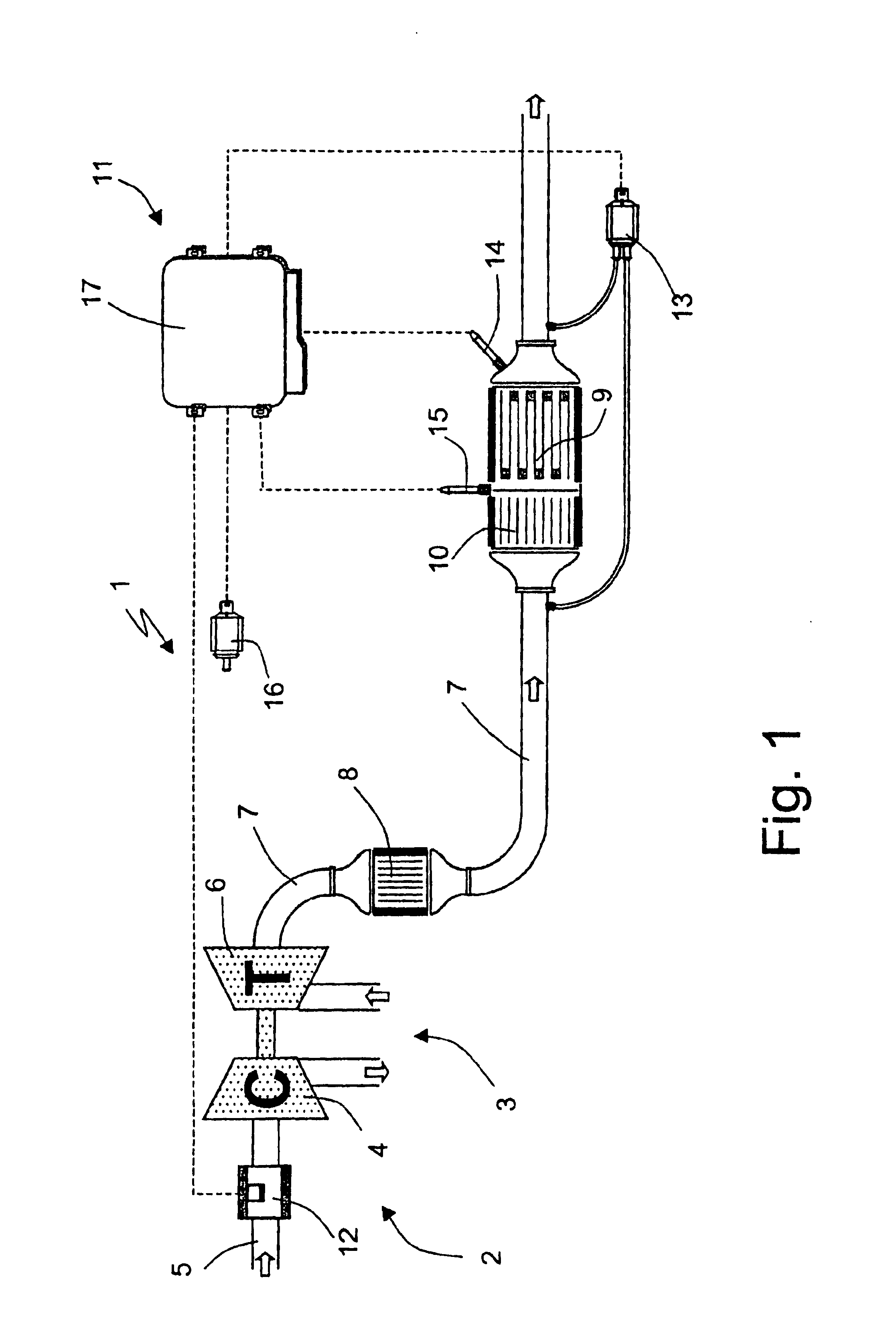
[0046]Number 1 in FIG. 1 indicates as a whole an exhaust system of an engine 2, in particular a diesel engine. In the non-limiting example shown, diesel engine 2 in FIG. 1 is a turbocharged type, and comprises a turbocharger 3 defined by a compressor 4 located along an air intake conduit 5, and by a turbine 6 connected to compressor 4 and located along an exhaust conduit 7.

[0047]Exhaust system 1 comprises an oxidizing catalytic converter (pre-cat) 8 located along exhaust conduit 7, close to turbocharger 3; a particulate filter 9 located along exhaust conduit 7, downstream from pre-cat 8; and a further oxidizing catalytic converter (Front-cat) 10 located along exhaust conduit 7, upstream from particulate filter 9.

[0048]Alternatively, the functions of Front-cat 10 and particulate filter 9 may be performed by a single component known as a catalyzed particulate filter (not shown).

[0049]Particulate filter 9, whether it be separate from or integrated with Front-cat 10, may be provided wit...


PUM

PropertyMeasurementUnit
temperaturesaaaaaaaaaa
physical-chemical propertiesaaaaaaaaaa
temperatureaaaaaaaaaa

Abstract

A method of determining the amount of particulate accumulated in a particulate filter, is based on determining possible variations in the spatial distribution and/or physical-chemical properties of the particulate as a function of engine operating conditions and past particulate accumulation in the particulate filter. A number of reference values defining a relationship between the amount of particulate accumulated in the particulate filter and the pressure drop across the particulate filter are mapped, each of the reference values relating to a respective steady engine operating condition in which particulate is accumulated in the particulate filter. In a given engine operating condition, an operating value of the parameter is then determined as a function of the reference value of the parameter relative to the same steady engine operating condition, and of past particulate accumulation in the particulate filter.

Description

[0001]The present invention relates to a method of determining the amount of particulate accumulated in a particulate filter.[0002]The present invention may be used to advantage, though not exclusively, in automotive applications, and particularly in internal combustion engines, especially diesel engines, to which the following description refers purely by way of example.[0003]The present invention, in fact, may also be used in other than automotive applications, as for filtering particulate emitted by any system equipped with particulate filters, such as fuel burners, etc.BACKGROUND OF THE INVENTION[0004]As is known, in many countries, the regulations governing atmospheric pollution are becoming increasingly strict with regard to the composition of internal combustion engine exhaust gas.[0005]In the case of diesel engines in particular, the main problems are posed not so much by carbon monoxide (CO) and hydrocarbons (HC) as by nitric oxides (NOx) and particulate in the exhaust gas....

Claims


Application Information

Patent Timeline
Patent Type & Authority Patents(United States)
IPC IPC(8): F01N9/00F01N11/00F01N3/035F01N7/02F01N7/00F02B37/00G01N15/08F01N13/02
CPCF01N3/035F01N9/002F01N11/002F01N13/009F01N13/0097F01N13/0093F02B37/00F02D2041/1411F02D2200/0812G01N2015/084Y02T10/47Y10S55/30Y02T10/40
Inventor BORETTO, GIANMARCOCORRIAS, SILVIO
Owner CENT RICERCHE FIAT SCPA
Why Eureka
Try Eureka