
Occupant restraint device control system and method

a technology for occupant restraint devices and control systems, which is applied in the direction of belt control systems, electric devices, vehicle seats, etc., can solve the problems of children and infants being left alone, pets which are more often left alone in hot vehicles without adequate ventilation, and the temperature in the vehicle rises, so as to reduce the intensity of light striking and reduce the intensity of light reflecting

Inactive Publication Date: 2005-09-13
AUTOMOTIVE TECH INT
View PDF121 Cites 43 Cited by
  • Summary
  • Abstract
  • Description
  • Claims
  • Application Information

AI Technical Summary

Benefits of technology

[0044]The invention also includes methods and arrangements for obtaining information about an object in a vehicle. This determination is used in various methods and arrangements for, e.g., controlling occupant protection devices in the event of a vehicle crash. The determination can also used in various methods and arrangements for, e.g., controlling heating and air-conditioning systems to optimize the comfort for any occupants, controlling an entertainment system as desired by the occupants, controlling a glare prevention device for the occupants, preventing accidents by a driver who is unable to safely drive the vehicle and enabling an effective and optimal response in the event of a crash (either oral directions to be communicated to the occupants or the dispatch of personnel to aid the occupants). Thus, one objective of the invention is to obtain information about occupancy of a vehicle and convey this information to remotely situated assistance personnel to optimize their response to a crash involving the vehicle and / or enable proper assistance to be rendered to the occupants after the crash.
[0061]If the object is a door, the resonator is arranged in a surface facing the door such that closure of the door prevents emission of the energy signal therefrom, in which case, the information obtained about the door is an indication of whether the door is open or closed.
[0066]4. To provide an occupant sensing system which detects the presence of a life form in a vehicle and under certain conditions, activates a vehicular warning system or a vehicular system to prevent injury to the life form
[0070]8. To determine the location of the ears of one or more vehicle occupants and to use that information to control the entertainment system, e.g., the speakers, so as to improve the quality of the sound reaching the occupants' ears through such methods as noise canceling sound.
[0090]28. To determine the location of the eyes of a vehicle occupant and the direction of a light source such as the headlights of an oncoming vehicle or the sun and to cause a filter to be placed in such a manner as to reduce the intensity of the light striking the eyes of the occupant.
[0091]29. To determine the location of the eyes of a vehicle occupant and the direction of a light source such as the headlights of a rear approaching vehicle or the sun and to cause a filter to be placed in such a manner as to reduce the intensity of the light reflected from the rear view mirrors and striking the eyes of the occupant.

Problems solved by technology

It is a problem in vehicles that children and infants are sometimes left alone, either intentionally or inadvertently, and the temperature in the vehicle rises.
This same problem also arises for pets which are more often left alone in a hot vehicle without adequate ventilation.
Another problem which has unfortunately arisen relates to the theft of vehicles.
There have been incidents when a thief waits in a vehicle until the driver of the vehicle enters the vehicle and then forces the driver to provide the keys to the vehicle and exit the vehicle.
Also, a child in a rear facing child seat, which is placed on the right front passenger seat, is in danger of being seriously injured if the passenger airbag deploys.
In addition to eliminating the disturbance of unnecessary airbag deployments, the cost of replacing these airbags will be excessive if they all deploy in an accident.
The danger of deployment-induced injuries will exist for side impact airbags as they now do for frontal impact airbags.
Once the system is operational, it would be logical for the system to also incorporate the airbag electronic sensor and diagnostics system (SDM) since it needs to interface with SDM anyway and since they could share computer capabilities which will result in a significant cost saving to the auto manufacturer.
This technology could provide input data to a pattern recognition system but it has limitations related to temperature.
The sensing of the child could pose a problem if the child is covered with blankets.
It also might not be possible to differentiate between a rear facing child seat and a forward facing child seat.
In all cases, the technology will fail to detect the occupant if the ambient temperature reaches body temperature as it does in hot climates.
Its main drawback is cost which is considerably above that of ultrasonic or passive infrared systems.
The wavelength of a particular radar system can limit the ability of the pattern recognition system to detect object features smaller than a certain size.
Once again, however, there is some concern about the health effects of radar on children and other occupants.
The ultrasonic system is the least expensive and potentially provides less information than the optical or radar systems due to the delays resulting from the speed of sound and due to the wave length which is considerably longer than the optical (including infrared) systems.

Method used


Image

  • Occupant restraint device control system and method
  • Occupant restraint device control system and method
  • Occupant restraint device control system and method

Examples


Embodiment Construction

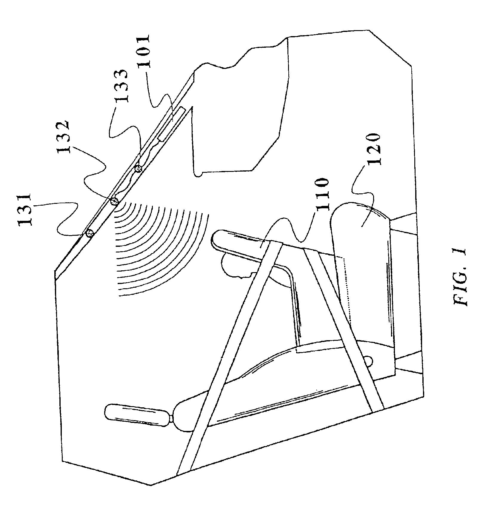
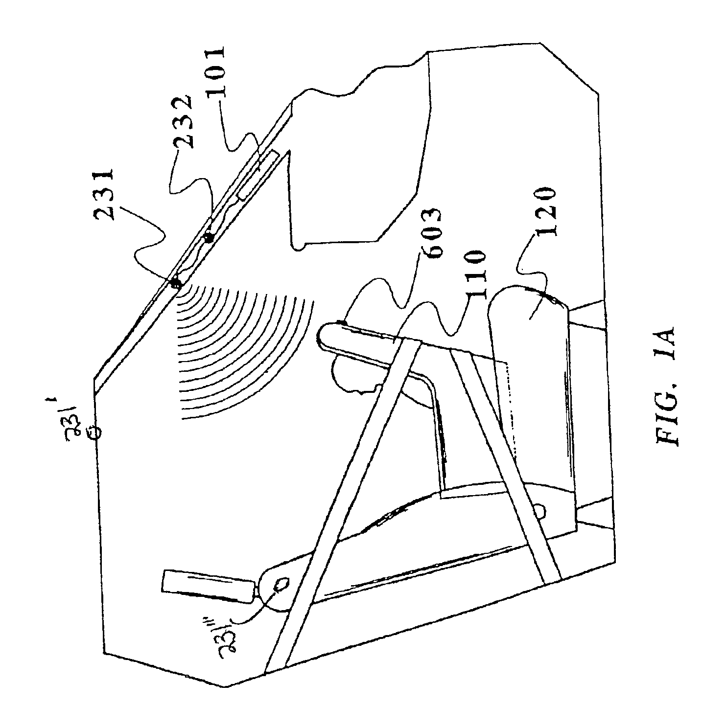
[0139]Referring to the accompanying drawings wherein the same reference numerals refer to the same or similar elements, FIG. 1 is a side view, with parts cutaway and removed of a vehicle showing the passenger compartment containing a rear facing child seat 110 on a front passenger seat 120 and a preferred mounting location for a first embodiment of a vehicle interior monitoring system in accordance with the invention. The interior monitoring system is capable of detecting the presence of an occupant and the rear facing child seat 110. In this embodiment, three transducers 131, 132 and 133 are used, although any number of wave-transmitting transducers or radiation-receiving receivers may be used. Such transducers or receivers may be of the type which emit or receive a continuous signal, a time varying signal or a spacial varying signal such as in a scanning system. One particular type of radiation-receiving receiver for use in the invention is a receiver capable of receiving electrom...


PUM


Abstract

Control system for controlling an occupant restraint device effective for protection of an occupant of the seat including a receiving device arranged in the vehicle for obtaining information about contents of the seat and generating a signal based on any contents of the seat, a different signal being generated for different contents of the seat when such contents are present on the seat, an analysis unit such as a microprocessor coupled to the receiving device for analyzing the signal in order to determine whether the contents of the seat include a child seat, whether the contents of the seat include a child seat in a particular orientation and / or whether the contents of the seat include a child seat in a particular position, and a deployment unit coupled to the analysis unit for controlling deployment of the occupant restraint device based on the determination by the analysis unit. The analysis unit can be programmed to determine whether the contents of the seat include a child seat in a rear-facing position, in a forward-facing position, a rear-facing child seat in an improper orientation, a forward-facing child seat in an improper orientation, and the position of the child seat relative to one or more of the occupant restraint devices.

Description

CROSS REFERENCE TO RELATED APPLICATIONS[0001]This application is a continuation-in-part of U.S. patent application Ser. No. 10 / 058,706 filed Jan. 28, 2002 which in turn is:[0002]1) a continuation-in-part of U.S. patent application Ser. No. 09 / 891,432 filed Jun. 26, 2001 now U.S. Pat. No. 6,513,853, which in turn is a continuation-in-part of U.S. patent application Ser. No. 09 / 838,920 filed Apr. 20, 2001 now U.S. Pat. No. 6,778,672, which in turn is a continuation-in-part of U.S. patent application Ser. No. 09 / 563,556 filed May 3, 2000 now U.S. Pat. No. 6,474,683, which is a continuation-in-part of U.S. patent application Ser. No. 09 / 437,535 filed Nov. 10, 1999 now U.S. Pat. No. 6,712,387 which in turn is a continuation-in-part of U.S. patent application Ser. No. 09 / 047,703 filed Mar. 25, 1998, now U.S. Pat. No. 6,039,139, which in turn is:[0003]a) a continuation-in-part of U.S. patent application Ser. No. 08 / 640,068 filed Apr. 30, 1996, now U.S. Pat. No. 5,829,782, which in turn is ...

Claims


Application Information

Patent Timeline
IPC IPC(8): B60N2/00B60N2/26B60J10/00B60N2/02B60N2/48B60R22/18B60R21/01B60R22/20B60N2/28B60R16/02B60R11/02B60R1/08E05F15/00G01F23/296G01F23/00G01F23/20G01S17/88G01S15/88G01S15/00G01S15/87G01S7/02G01S17/00G01S7/48G01S7/41G01S7/539G06K9/00B60R21/16B60R22/00B60R21/20B60R22/48B60R21/26B60R1/12G01S13/00G01S15/04G01S15/06G01S13/04G01S17/89B60R16/037B60R21/013B60R21/0132B60R21/0134B60R21/015B60R21/215B60R21/231B60R21/276
CPCB60J10/00B60N2/0248B60N2/0276B60N2/2806B60N2/2863B60R1/088B60R11/0241B60R16/037B60R21/0134B60R21/0136B60R21/21656B60R21/276B60R22/20B60R25/25B60R25/252B60R25/255B60R25/257B60R2001/1223B60R2001/1253B60R2021/0027B60R2021/01315B60R2021/23153B60R2021/26094B60R2021/2765B60R2022/208B60R2022/4825E05Y2400/664E05Y2900/55G01F23/20G01F23/2962G01S7/417G01S7/4802G01S7/539G01S13/04G01S15/04G01S15/06G01S15/87G01S15/88G01S17/88G01S17/89G10K2210/1282G10K2210/3219B60R21/01554B60R21/01548B60R21/01536B60R21/01516B60R21/01534B60R21/01538B60R21/01542B60R21/01552B60R21/0154B60R21/01544E05F15/43E05F15/431E05F2015/433B60N2/888B60N2/853G01F23/804G06V40/10B60N2/0272B60N2/0268B60N2/02246B60N2/0026B60N2/0023B60N2210/20B60N2210/26B60N2/0028B60N2/0022B60N2/0278B60N2/002B60N2/28
Inventor BREED, DAVID S.DUVALL, WILBUR E.JOHNSON, WENDELL C.
Owner AUTOMOTIVE TECH INT
Features
  • Generate Ideas
  • Intellectual Property
  • Life Sciences
  • Materials
  • Tech Scout
  • Unparalleled Data Quality
  • Higher Quality Content
  • 60% Fewer Hallucinations
Learn More