Method for compensating for pressure differences across valves in cassette type IV pump

Inactive Publication Date: 2005-09-13
ICU MEDICAL INC
View PDF36 Cites 72 Cited by
  • Summary
  • Abstract
  • Description
  • Claims
  • Application Information

AI Technical Summary

Benefits of technology

[0010]In accord with the present invention, a pressure compensated pump is defined for maintaining an accurate delivery of fluid to a patient when a differential pressure exists between an inlet and outlet of the pump. The pump includes a fluid drive unit that is adapted to couple with a fluid line and to force fluid from a source for infusion into the patient through the fluid line. A control unit is coupled to the fluid drive unit to control its operation. A first pressure sensor monitors the inlet pressure to the pump, and a second pressure sensor monitors the outlet pressure of the pump. Both the first and the second pressure sensors are electrically coupled to the control unit. The control unit is programmed to determine a differenti

Problems solved by technology

However, when the pressures at the pump inlet and outlet vary substantially, the delivery accuracy of cassette pumps degrade.
If the delivery rate is relatively low, as is often the case in pediatric applications, and if the differential pressure exceeds 3 psi, accuracy is significantly impaired, and retrograde flow can occur.
In retrograde flow, fluid moves from the patient's vascular system towards the pump, which can result in blood from a patient being drawn out of the patient's body and into the IV line.
Eve

Method used


Image

  • Method for compensating for pressure differences across valves in cassette type IV pump
  • Method for compensating for pressure differences across valves in cassette type IV pump
  • Method for compensating for pressure differences across valves in cassette type IV pump

Examples


Example

Overview of the Present Invention

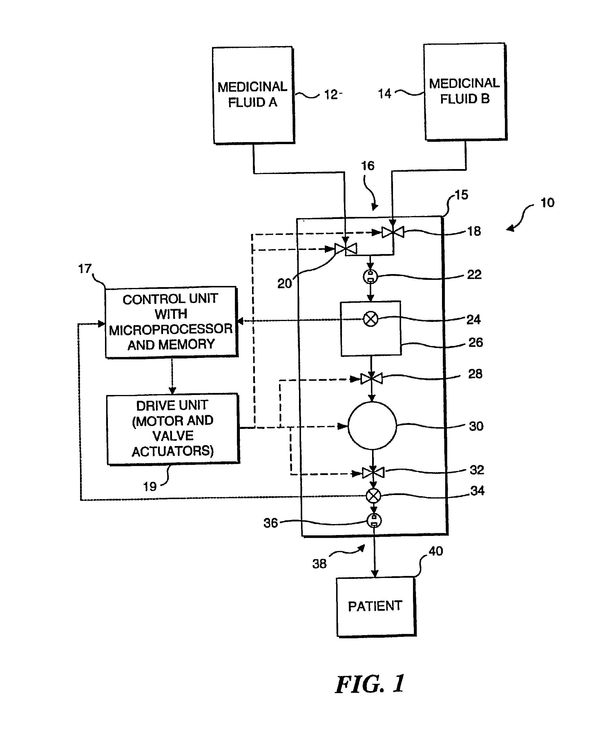
[0033]The present invention employs an algorithm to compensate for a differential pressure between the inlet and outlet of a cassette type infusion pump to enhance the accuracy of the pump, particularly at low flow rates. A preferred embodiment of the present invention will be incorporated in Abbott Laboratories' PLUM A+™ Infusion Pump, which will be used in conjunction with its PLUM™ Cassette. The algorithm used in this embodiment has been empirically determined for these specific products. However, it should be noted that a similar algorithm can be empirically determined for other designs of infusion cassettes and infusion pumps. The present invention is thus not in any way limited to the specific design of the pump and cassette discussed below.

[0034]The terms “proximal” and “inlet” as used herein in connection with the following description and the claims that follow synonymously refer to the portion of the cassette that is coupled in fluid commun...


PUM


Abstract

A pump used to infuse a fluid into a patient is controlled in accordance with an algorithm that enables a microprocessor to monitor and adjust each pump cycle to compensate for a differential pressure between the pump's inlet and outlet. The algorithm defines a fluid delivery protocol that is applied in controlling the operation of the pump to achieve a desired rate, volume, and timing of the fluid infusion. Fluid is delivered by the pump when a plunger compresses an elastomeric membrane overlying a fluid chamber. Due to the small volume of the chamber, an incremental change in the plunger position before the delivery stroke produces a significant change in the delivery pressure. At the beginning of a pump cycle, the microprocessor determines the differential pressure between the inlet and outlet of the pump, and adjusts the plunger position before the delivery stroke to compensate for the differential pressure. A retraction of the plunger from the home position decreases the delivery pressure of the fluid, and an advancement of the plunger increases it. After the position of the plunger is adjusted to compensate for the differential pressure, the pump cycle proceeds. Following the plunger stroke, the outlet pressure is used to determine the actual volume of fluid delivered. The duration of the plunger stroke in the next pump cycle is adjusted to compensate for any volume delivery error produced by the differential pressure compensation.

Description

[0001]This is a continuation of U.S. patent application Ser. No. 09 / 464,812, filed Dec. 17, 1999 now U.S. Pat. No. 6,497,680, now allowed.FIELD OF THE INVENTION[0002]The present invention generally relates to a method and apparatus used for compensating pressure differences between an inlet and outlet of a pump, and more specifically, to a method and apparatus for compensating pressure differences across the inlet and the outlet of a cassette type infusion pump used to deliver medicinal fluids intravascularly.BACKGROUND OF THE INVENTION[0003]Various types of pumps are used by medical personnel to infuse drugs into a patient's body. Of these, cassette infusion pumps are often preferred because they provide a more accurately controlled rate and volume of drug infusion than other types of infusion pumps. A cassette pump employs a disposable plastic cassette coupled in a fluid line extending between a drug reservoir and the patient's body.[0004]In one prior art design of a cassette infu...

Claims


Application Information

Patent Timeline
IPC IPC(8): A61M5/168A61M5/172A61M5/142A61M5/00F04B49/08F04B13/00F04B49/00F04B49/06G01P21/00G05D16/20
CPCA61M5/14224A61M5/16809G05D16/2046A61M5/16827A61M2205/12A61M2205/3355A61M2205/50A61M5/365
Inventor HOLST, PETER A.KRAJEWSKI, DAVID A.MASKE, RUDOLPH J.
Owner ICU MEDICAL INC
Why Eureka
Try Eureka