Radio frequency power amplifier

a technology of radio frequency power amplifier and efficiency improvement, which is applied in the direction of amplifier combination, high frequency amplifier, gated amplifier, etc., can solve the problems of reducing efficiency, power consumption of switch, and introducing inevitable efficiency loss, etc., and achieves low output power and high output power.

Inactive Publication Date: 2005-09-13
RENESAS ELECTRONICS CORP
View PDF7 Cites 62 Cited by
  • Summary
  • Abstract
  • Description
  • Claims
  • Application Information

AI Technical Summary

Benefits of technology

[0009]Accordingly, an object of the present invention is to provide a radio frequency power amplifier which may not introduce radio frequency loss when switching power amplifiers (amplifying elements) for high output power and low output power.
[0010]The object of the present invention may be efficiently achievable by connecting each of first-stage matching networks to the output node of respective one of at least two power amplifier units having a different saturated output power level from each other and being used in operation by switching, connecting the output nodes of the first-stage matching networks together in parallel to make a junction, connecting a last-stage matching network between the junction and an output terminal, and forming the first-stage matching networks and the last-stage matching network so that impedance matching is established between the output impedance of the power amplifier unit in operation and the output characteristic impedance at the output terminal, for each of the at least two power amplifier units, when any one of the at least two power amplifier units is in operation and the other in stop of operation. By adopting such a means, the power amplifier units may satisfy the condition of impedance matching while supplying an output signal to the output terminal, without the need of inserting a radio frequency switch.
[0011]In addition, the object of the present invention may also be achieved by connecting each of other last-stage matching networks to an input node of respective one of at least two power amplifier units having a different saturated output power level from each other and being used in operation by switching, in addition to the connection to the above described output side thereof, connecting the input nodes of the last-stage matching networks together in parallel to make another junction, connecting another first-stage matching network between the another junction and an input terminal, and forming the other last-stage matching networks and the another first-stage matching network so that impedance matching is established between the input impedance of the power amplifier unit in operation and the input characteristic impedance at the input terminal, for each of the at least two power amplifier units, when any one of the at least two power amplifier units is in operation and the other in stop of operation. By adopting such a means, the power amplifier units may satisfy the condition of impedance matching while supplying an output signal to the output terminal, as well as may satisfy the condition of impedance matching while accepting an input signal from the input terminal.

Problems solved by technology

In this circuit design, the radio frequency switch SW1 is placed after the high and low output power amplifier components A161 and A162, so that inevitably the effective improvement of efficiency may not be sufficient because of decreased efficiency due to the loss at this section.
In addition, some electric power will be needed in order to operate the radio frequency switch SW1, power consumption of the switch may also introduce inevitable loss of efficiency.
The insertion loss of the radio frequency switch may also cause some decrease of efficiency, as similar to the output side.

Method used


Image

  • Radio frequency power amplifier
  • Radio frequency power amplifier
  • Radio frequency power amplifier

Examples


Embodiment Construction

[0029]A detailed description of some preferred embodiments shown in the accompanying drawings embodying the radio frequency power amplifier of the present invention will now be given, in greater details, by referring to the accompanying drawings.

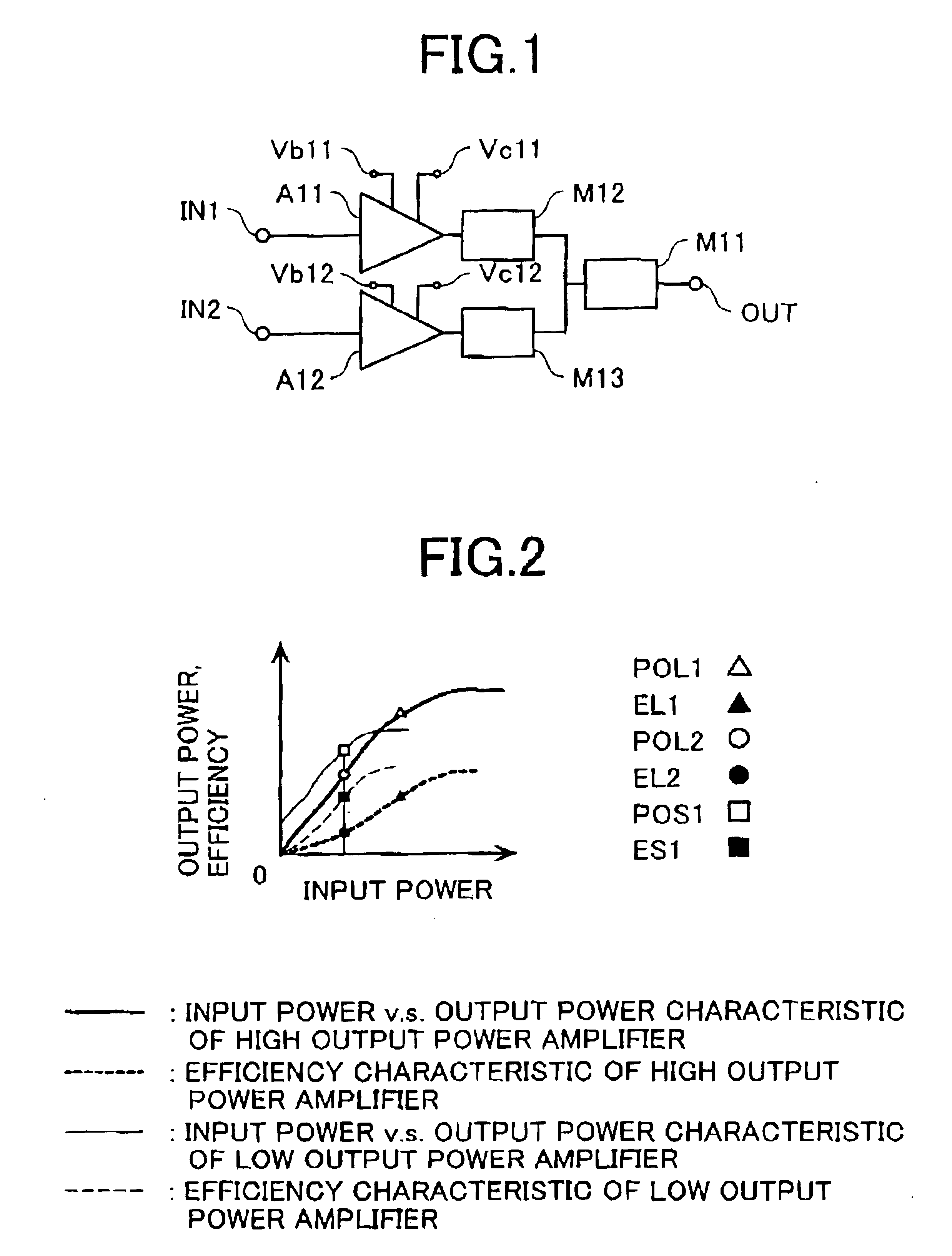
[0030]Now referring to FIG. 1, reference numeral A11 is designated to a high output power amplifier unit, A12 is to a small output power amplifier unit, M12 and M13 are first-stage matching networks connected to the output nodes of power amplifier unit A11 and power amplifier unit A12, respectively, M11 is to a last-stage matching network connected between the junction node of the output nodes of matching networks M12 and M13 and the output terminal OUT. The power amplifier unit A11 and power amplifier unit A12 are both formed of one single amplifier chip. An input signal will be fed to the power amplifier unit A11 via input terminal IN1, and to the power amplifier unit A12 via input terminal IN2. The power amplifier unit A11 incorporates ba...


PUM


Abstract

The present invention provides a radio frequency power amplifier which may not introduce radio frequency loss during switching power amplifier units between high and low output power levels. By connecting a first-stage matching network M12 and first-stage matching network M13 to respective output nodes of a power amplifier unit A11 and power amplifier unit A12 that either one operate by switching, connecting the output nodes of the first-stage matching network M12 and M13 in parallel, connecting a last-stage matching network M11 between the junction of M12 and M13 and the output terminal OUT, the first-stage matching networks M12, M13, and last-stage matching network M11 are formed, for both power amplifier units A11 and A12, so that impedance matching is established between the output terminal OUT and the power amplifier unit in operation when one unit is in operation the other is in stop of operation. The present invention allows switching from one power amplifier unit to the other without the need of a radio frequency switch.

Description

BACKGROUND OF THE INVENTION[0001]The present invention relates to an improved efficiency of radio frequency power amplifiers for use in portable cellular phone terminals and base stations incorporated in a mobile communication system.[0002]Recently, in the field of the mobile communication, scaling down in the size and weight is requested not only for the portable cellular terminals but also for the base stations. Along with this trend is further requested the improvement of the efficiency of the power amplifiers, which affects mostly the electric consumption of the whole system. The portable cellular phone terminal, which usually use a battery for their main power source, may have a major problem that requires to improve the efficiency of the phone terminal, by saving the power consumption in the power amplifier unit which drains the most power in the circuitry, in order for the terminal to sustain its operating time. In addition, since the radio frequency power amplifier are insta...

Claims


Application Information

Patent Timeline
Patent Type & Authority Patents(United States)
IPC IPC(8): H03F1/00H03F1/02H03F1/56H03F3/60H03F3/189H03F3/24H03F3/68
CPCH03F1/0277H03F1/56H03F1/565H03F3/602H03F3/72H03F2203/7209
Inventor OHNISHI, MASAMIMATSUMOTO, HIDETOSHITANOUE, TOMONORIKAGAYA, OSAMUSEKINE, KENJI
Owner RENESAS ELECTRONICS CORP
Why Eureka
Try Eureka