Calibration of an adaptive signal conditioning system

a signal conditioning and adaptive technology, applied in the field of adaptive signal conditioning systems, can solve the problems of affecting the overall performance of the adaptive predistortion technique, dynamic changes in the transfer characteristics of the feedback path, and distortion caused by the power amplifier, so as to maintain the output power accuracy of the power amplifier system, accurate control of gain, phase and/or delay, accurate linear output response

Inactive Publication Date: 2005-09-13
TELEFON AB LM ERICSSON (PUBL)
View PDF7 Cites 64 Cited by
  • Summary
  • Abstract
  • Description
  • Claims
  • Application Information

AI Technical Summary

Benefits of technology

[0022]It is another object of the invention to provide a mechanism for robust and efficient calibration of an adaptive signal conditioning system.
[0025]The general idea according to the invention is to provide robust and efficient calibration of an adaptive signal conditioning system by selectively inserting a well-defined reference signal into the feedback path, and calibrating the feedback path based on the reference signal. The use of a reference signal for calibration of the feedback path means that the effects of changes in the transfer characteristics of the feedback path due to factors such as variations in ambient temperature and component aging are effectively removed. In this way, the feedback signal transferred over the calibrated feedback path will be an accurate representation of the output signal of the forward path, thus allowing accurate adaptive signal conditioning.
[0029]The invention is generally applicable and may be implemented with any system that requires accurate adaptive signal conditioning. For example, the invention may be implemented with a power amplifier system for maintaining an absolutely accurate and linear output response. In this regard, it may be of particular interest to maintain the output power accuracy of the power amplifier system by calibrating the feedback path of the adaptive signal conditioning system with respect to gain. Another important example involves a multi-branch transmitter system, such as an adaptive antenna system or a transit diversity system, in which the invention is implemented for accurately controlling the gain, phase and / or delay. In an adaptive antenna system, the calibration according to the invention can be used for providing accurate gain and phase control. In a transmit diversity system, the invention can be used for accurate delay matching between different transmission branches.

Problems solved by technology

However, since the distortion caused by the power amplifier may change over time due to factors such as variations in ambient temperature and component aging, an adaptive predistortion scheme is employed to maintain the linearity.
In practice, however, the transfer characteristics of the feedback path changes dynamically due to variations in temperature and frequency such that the observed signal SOBS at the output of the feedback path no longer is an accurate representation of the output signal SOUT.
This may severely affect the overall performance of the adaptive predistortion technique.
In fact, dynamic changes in the transfer characteristics of the feedback path is a key problem affecting the very core of any adaptive signal conditioning system.
For example, this problem manifests itself with respect to the need to maintain a specified signal level at the output of the power amplifier or similar signal conversion system.
However, in practice, both GRX and GTX change due to factors such as temperature variations and component aging.
While this would not influence the predistortion parameter adaptation, it would result in an incorrect output signal since the altered transmission gain GTX=(GTXinitial+GTXchange) will be incorrect.
This also results in an incorrect output signal SOUT.
Pre-characterization however has the disadvantage that there is some uncertainty whether the gain compensation will remain accurate with the aging of the many components involved.
Another disadvantage is the time required during production to complete the characterization and / or to calculate the compensation coefficients.
Although the power detector components are relatively few compared to the complete transmission path, this represents tile same disadvantage as mentioned earlier, including uncertainty with aging and the time required in production.

Method used


Image

  • Calibration of an adaptive signal conditioning system
  • Calibration of an adaptive signal conditioning system
  • Calibration of an adaptive signal conditioning system

Examples


Embodiment Construction

Calibration of a General Adaptive Signal Conditioning System

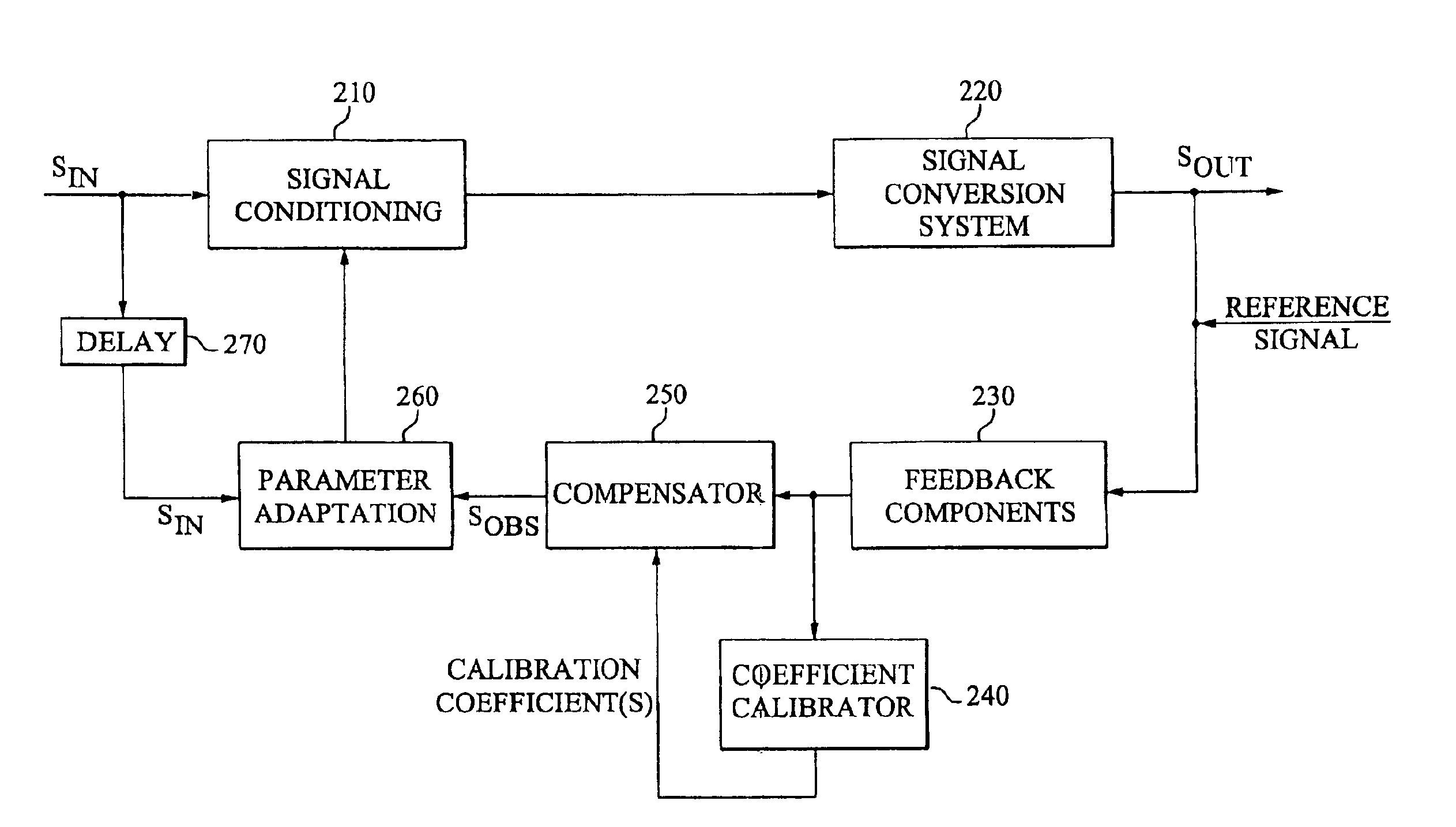
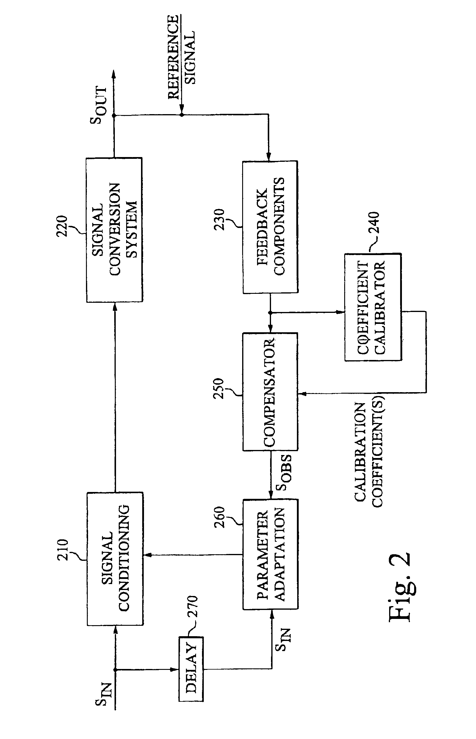
[0051]FIG. 2 is a schematic block diagram illustrating a general adaptive signal conditioning system according to the invention, applied in connection with an arbitrary signal conversion system. A signal conditioning block 210 is provided in the input signal path to a signal conversion system 220 for preconditioning the signal to be converted by the signal conversion system 220. In other words, the signal conditioning block 210 receives an input signal SIN and modifies the input signal according to the particular application. The resulting modified signal is then transferred to the signal conversion system 220, which converts the modified input signal into an output signal SOUT. The signal conversion system 220 may be any signal conversion system known to the art, performing signal conversion such as amplification, attenuation, frequency conversion, phase shifting or any other filtering that affects the signal characteristi...


PUM


Abstract

The invention provides robust and non-invasive calibration of an adaptive signal conditioning system having a signal conditioning block in the signal path to a signal conversion system, and a feedback path with a number of feedback components for enabling adaptation, by means of a parameter adaptation block, of the parameters used in the signal conditioning. In order to calibrate the feedback path, a well-defined reference signal is inserted into the feedback path, and an appropriate calibration coefficient is then determined by a coefficient calibrator in response to the received reference signal. The calibration coefficient is provided to a compensator, which effectively compensates for changes in the transfer characteristics of the feedback path due to factors such as variations in ambient temperature and component aging. Accordingly, the feedback signal transferred over the calibrated feedback path will be an accurate representation of the output signal of the signal conversion system, thus allowing accurate adaptive signal conditioning.

Description

[0001]This application is the U.S. national phase of international application PCT / SE02 / 01440 filled in English 09 Aug. 2002, which designated the U.S. PCT / 02 / 01440 claims priority to SE Application No. 0102885-1, filed 28 Aug. 2001. The entire contents of these applications are incorporated herein by reference.TECHNICAL FIELD OF THE INVENTION[0002]The present invention generally relates to an adaptive signal conditioning system and a method for calibration of such a system, as well as the implementation of adaptive signal conditioning techniques in a power amplifier system and a multi-branch transmitter system.BACKGROUND OF THE INVENTION[0003]Adaptive signal conditioning systems can be found in all areas of electronics and communication, and are generally used for adaptively conditioning the input signal to a signal conversion system such as an amplifier chain or any other suitable system in order to continuously provide a desired output signal of the overall system.[0004]Predistor...

Claims


Application Information

Patent Timeline
Patent Type & Authority Patents(United States)
IPC IPC(8): H03F1/32
CPCH03F1/3247
Inventor LEYONHJELM, SCOTTBJORK, VIMARGRASS, JOHNNEOVIUS, LENNARTLEATHER, PAUL
Owner TELEFON AB LM ERICSSON (PUBL)
Why Eureka
Try Eureka