Al technical title is built by PatSnap Al team. It summarizes the technical point description of the patent document.
a technology for home security and administration platforms, applied in the field of home security systems, can solve the problems of wasting civic resources, needlessly placing citizens in danger, and further cost, and actual emergency situations may go unattended
Inactive Publication Date: 2005-09-13
AMERICAN TELEPHONE & TELEGRAPH CO
View PDF9 Cites 51 Cited by
Summary
Abstract
Description
Claims
Application Information
AI Technical Summary
This helps you quickly interpret patents by identifying the three key elements:
Problems solved by technology
Method used
Benefits of technology
[0019]Thus, the present invention utilizes a smart network to administer security systems for residences and places of business that substantially eliminate false alarms and dispatches the most appropriate personnel for expeditiously responding to detected security breaches.
Problems solved by technology
However, due to a variety of reasons, including the intense pressure that may accompany the job, security system monitoring personnel often forego the verification protocol and proceed immediately to dispatching the local authorities, including either the local police department or fire department.
As a result, police and firefighting personnel have been dispatched in response to false alarms, thus squandering civic resources and needlessly placing citizens in peril who are in actual need of such services.
There is even a further cost, whereby actual emergency situations may go unattended if emergency services have been previously dispatched to a false alarm that has not been properly canceled.
The increase in false alarms incurs a financial cost to both the residential owner who must pay a civil penalty for false alarms over a predetermined threshold (three, for example) within a one-year period and to taxpayers in general who bear the burden of mis-allocated resources.
Further still, many instances have occurred in which police or firefighting personnel from the wrong jurisdiction have been dispatched, thus compromising the response time to an actually emergency situation.
Method used
Image
Click on the blue label to locate the original text in one second.
Reading with bidirectional positioning of images and text.
Examples
Embodiment Construction
[0025]Before beginning a detailed description of the invention, it should be noted that, when appropriate, like reference numerals and characters may be used to designate identical, corresponding or similar components in differing figure drawings. Further, in the detailed description to follow, example embodiments and values may be given, although the present invention is not limited thereto.
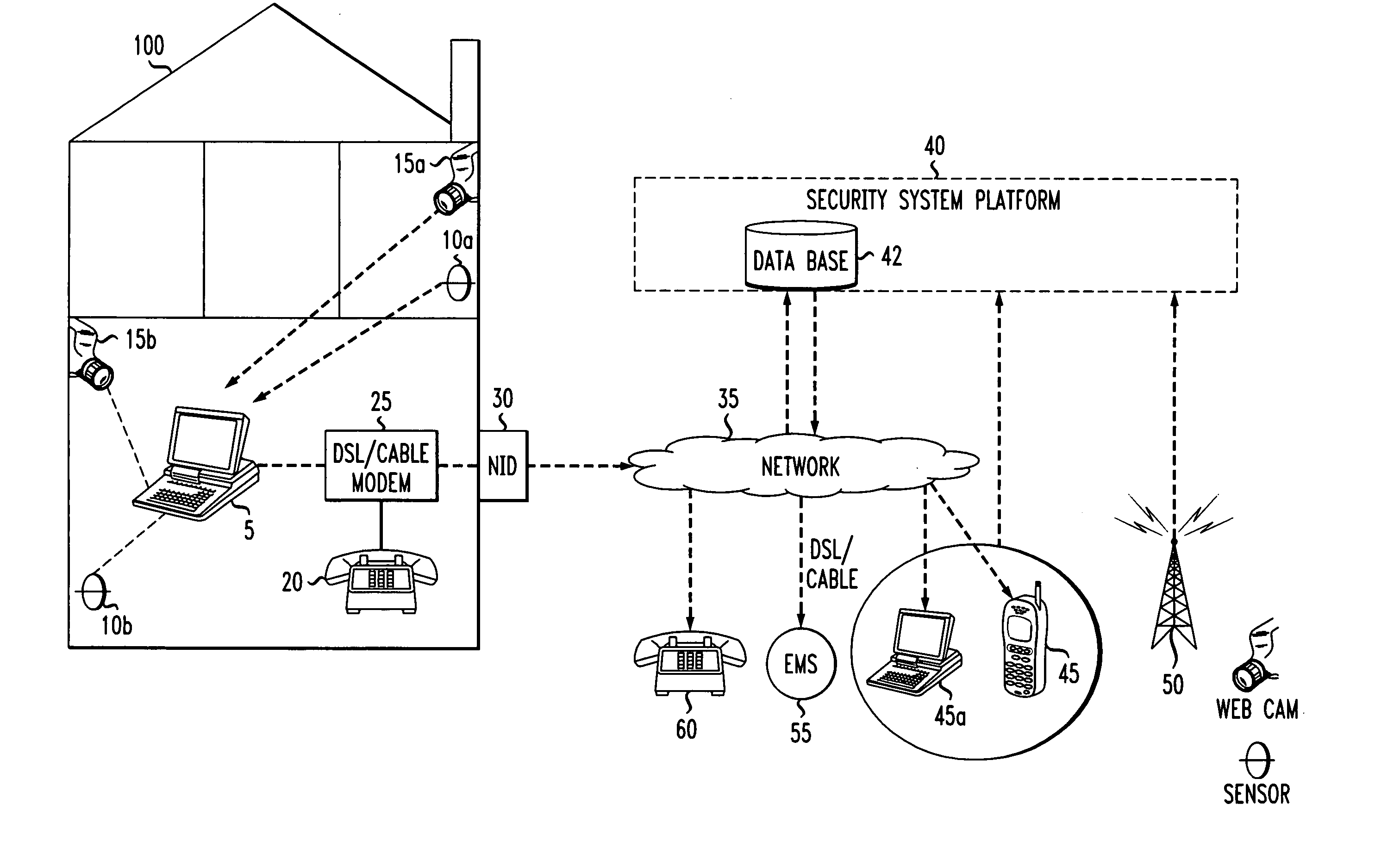
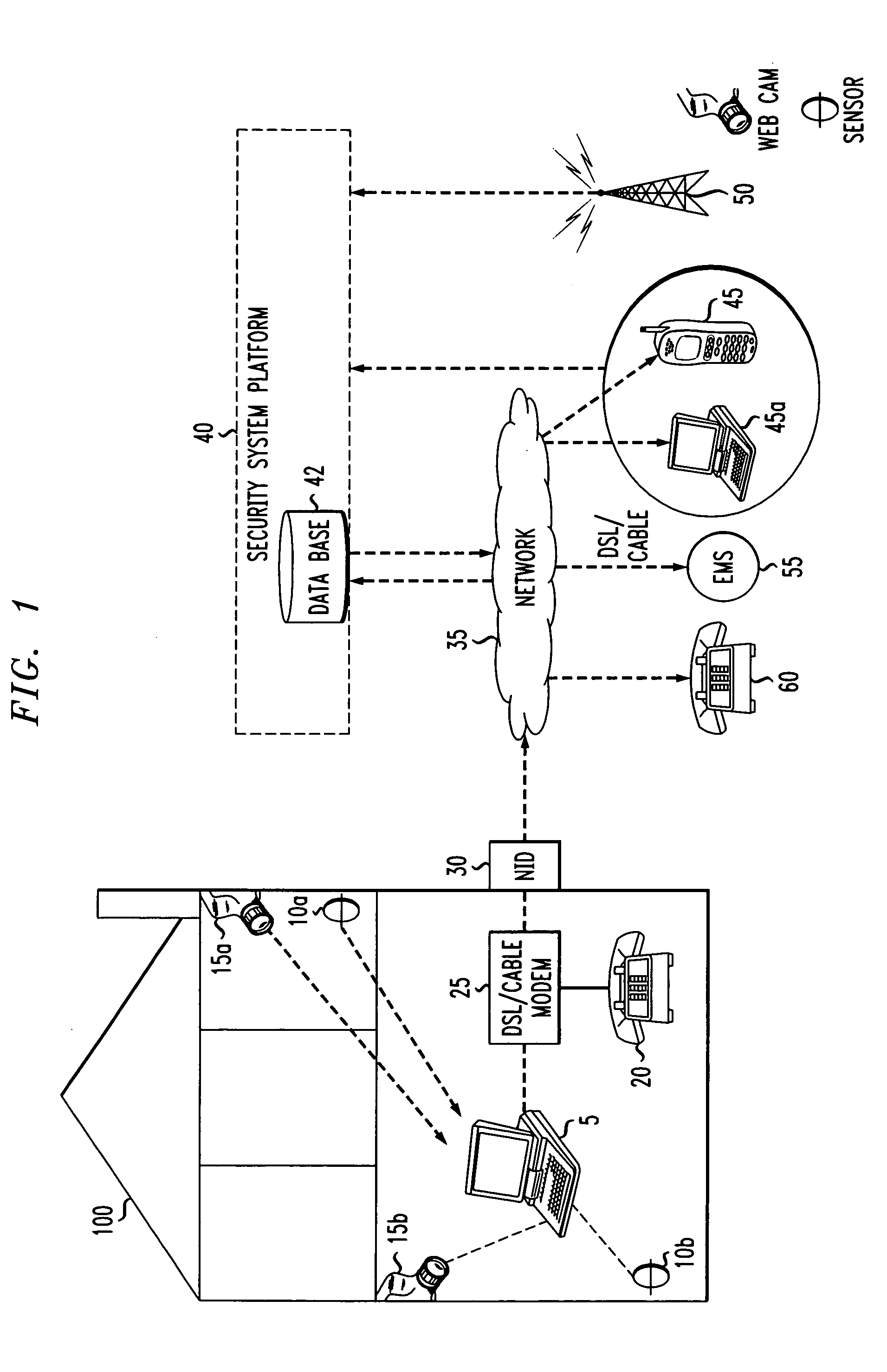
[0026]FIG. 1 shows an example embodiment of the present invention, including a home security system and network administrator. The security system is located in a building structure 100, which may interchangeably be a residence or a place of business. Though for the sake of the present description, reference will be made to residence 100.
[0027]A home security system 1 may be located in residence 100 and include a computer 5; detectors 10a and 10b, which may include motion detectors and heat sensors; security video cameras 15a and 15b; and network interface device (NID) 30, as well as various win...
PUM
Abstract
A network may receives tracking information of various emergency services personnel, so that when a security breach has occurred at a residence or place of business, the network receives a surveillance profile from a home computer that is disposed where the detector is located, and dispatch the most geographically appropriate emergency services personnel as determined based on the tracking information. The surveillance profile may include its address, location within the residence of place of business, and a physical description or layout of the premises in which the sensor is located. Then, a verification protocol is initiated by calling a predetermined sequence of telephone numbers set by the subscriber to the security system. Dispatching of the appropriate emergency services personnel includes the network accessing a security platform database to find corresponding emergency services personnel to respond to the detected security breach in accordance with the information received in the surveillance profile.
Description
CROSS-REFERENCE TO RELATED APPLICATION[0001]This application is a continuation of U.S. application Ser. No. 09 / 978,153, filed Oct. 16, 2001 and allowed as of Jul. 28, 2003 now U.S. Pat. No. 6,693,530.FIELD OF THE INVENTION[0002]The invention relates to home security systems, including the detecting of security and safety breaches, remote monitoring thereof, and the dispatching of the proper authorities in response to a security and / or safety breach.BACKGROUND OF THE INVENTION[0003]Many security systems include multiple video cameras, motion detectors, heat sensors, as well as various door and window traps that have been placed in a building structure by a security company or security system vendor. Such a building structure may include, but is in no way limited to, houses, apartment buildings, hotels, office buildings, and stores. The video cameras, motion detectors, heat sensors, and door and window traps, which may be referred to generally as “security equipment”, may be monitored...
Claims
Application Information
Patent Timeline
Application Date:The date an application was filed.
Publication Date:The date a patent or application was officially published.
First Publication Date:The earliest publication date of a patent with the same application number.
Issue Date:Publication date of the patent grant document.
PCT Entry Date:The Entry date of PCT National Phase.
Estimated Expiry Date:The statutory expiry date of a patent right according to the Patent Law, and it is the longest term of protection that the patent right can achieve without the termination of the patent right due to other reasons(Term extension factor has been taken into account ).
Invalid Date:Actual expiry date is based on effective date or publication date of legal transaction data of invalid patent.