Ram moving method for hydraulic machine, ram movement controller, method for preventing trapping of axial plunger pump used for the machine, and the pump

a technology of ram movement and hydraulic machine, which is applied in the direction of positive displacement liquid engine, fluid coupling, servomotor, etc., can solve the problems of shock generation on the ram, ram dead time is not constant, and the ram is dead time occurs. , to achieve the effect of preventing vibration and preventing nois

Inactive Publication Date: 2005-09-20
AMADA CO LTD
View PDF11 Cites 3 Cited by
  • Summary
  • Abstract
  • Description
  • Claims
  • Application Information

AI Technical Summary

Benefits of technology

[0041]According to the axial plunger pump confinement prevention method and the axial pump plunger therefor of the present invention, the valve plate is provided to be slightly rotatable in the rotation direction of the driving shaft and the cylinder block and the top dead center position of the plunger is o

Problems solved by technology

Due to this, dead time occurs to the ram before actuating the two-way pump, supplying hydraulic oil to the double acting cylinder and moving the ram.
Because of this ram dead time, a shock is generated on the ram.
However, the hydraulic power unit which employs such a two-way pump has a disadvantage in that ram dead time is not constant but varies depending on the operating state of the ram just before the dead time.
That is, according to the ram moving method by utilizing constant timer time, a shock is generated because of too short timer time or, conversely, that time is adversely influenced by too lo

Method used


Image

  • Ram moving method for hydraulic machine, ram movement controller, method for preventing trapping of axial plunger pump used for the machine, and the pump
  • Ram moving method for hydraulic machine, ram movement controller, method for preventing trapping of axial plunger pump used for the machine, and the pump
  • Ram moving method for hydraulic machine, ram movement controller, method for preventing trapping of axial plunger pump used for the machine, and the pump

Examples


Embodiment Construction

[0051]Embodiments of this invention will be described hereinafter in detail based on the drawings.

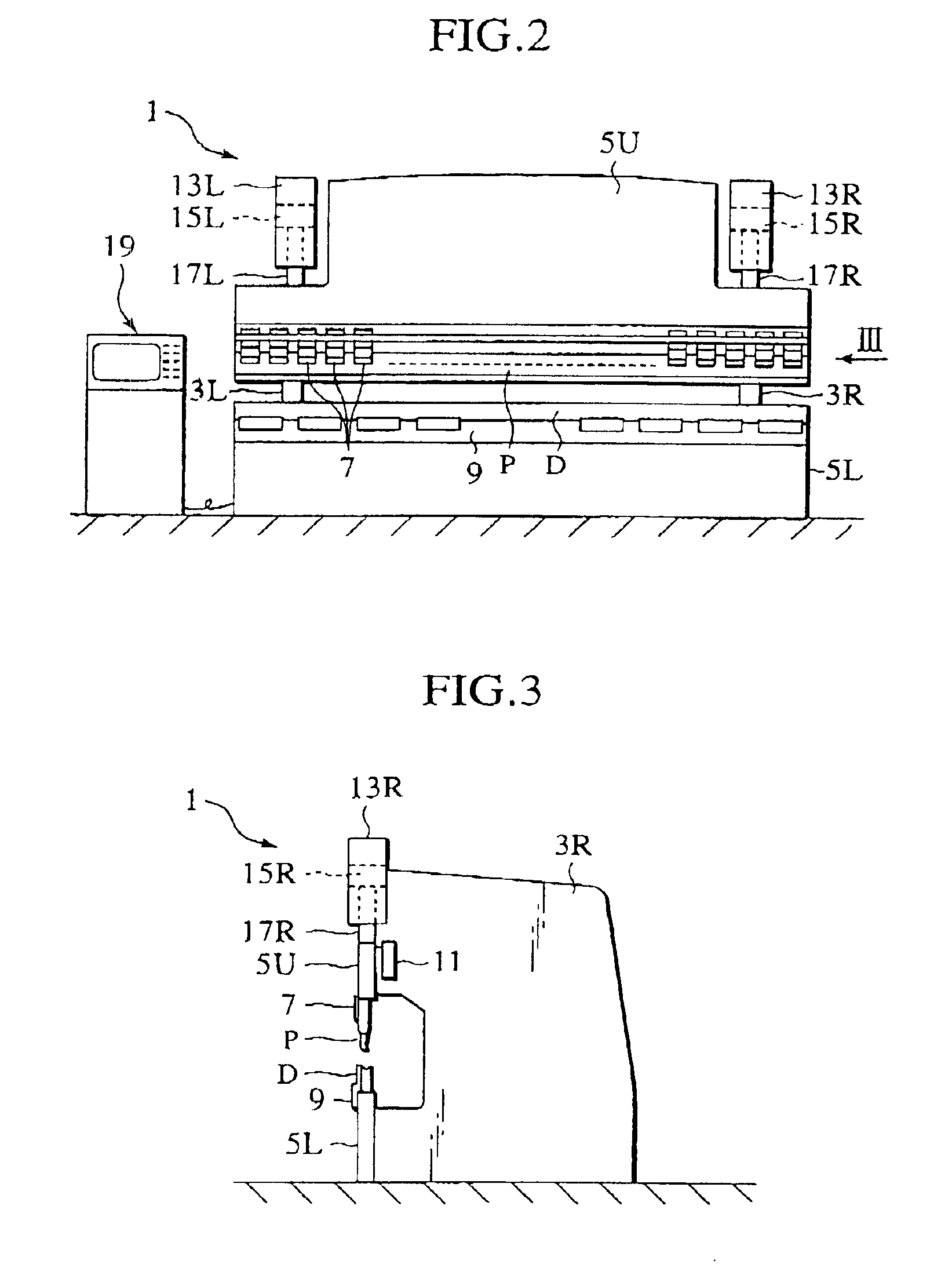
[0052]FIG. 2 and FIG. 3 show an overall oil hydraulic press brake 1 as one example of a hydraulic power unit. This press brake has side plates 3L and 3R at left and right sides respectively, an upper table 5U, which serves as a ram, vertically movably provided on the upper front end surfaces of the side plates 3L and 3R, and a lower table fixed to the lower front surfaces of the side plates 3L and 3R.

[0053]A punch P is provided on the lower end portion of the upper table 5U through intermediate plates 7 in an exchangeable manner. In addition, a die D is provided on the upper end portion of the lower table 5L through a die base 9 in an exchangeable manner

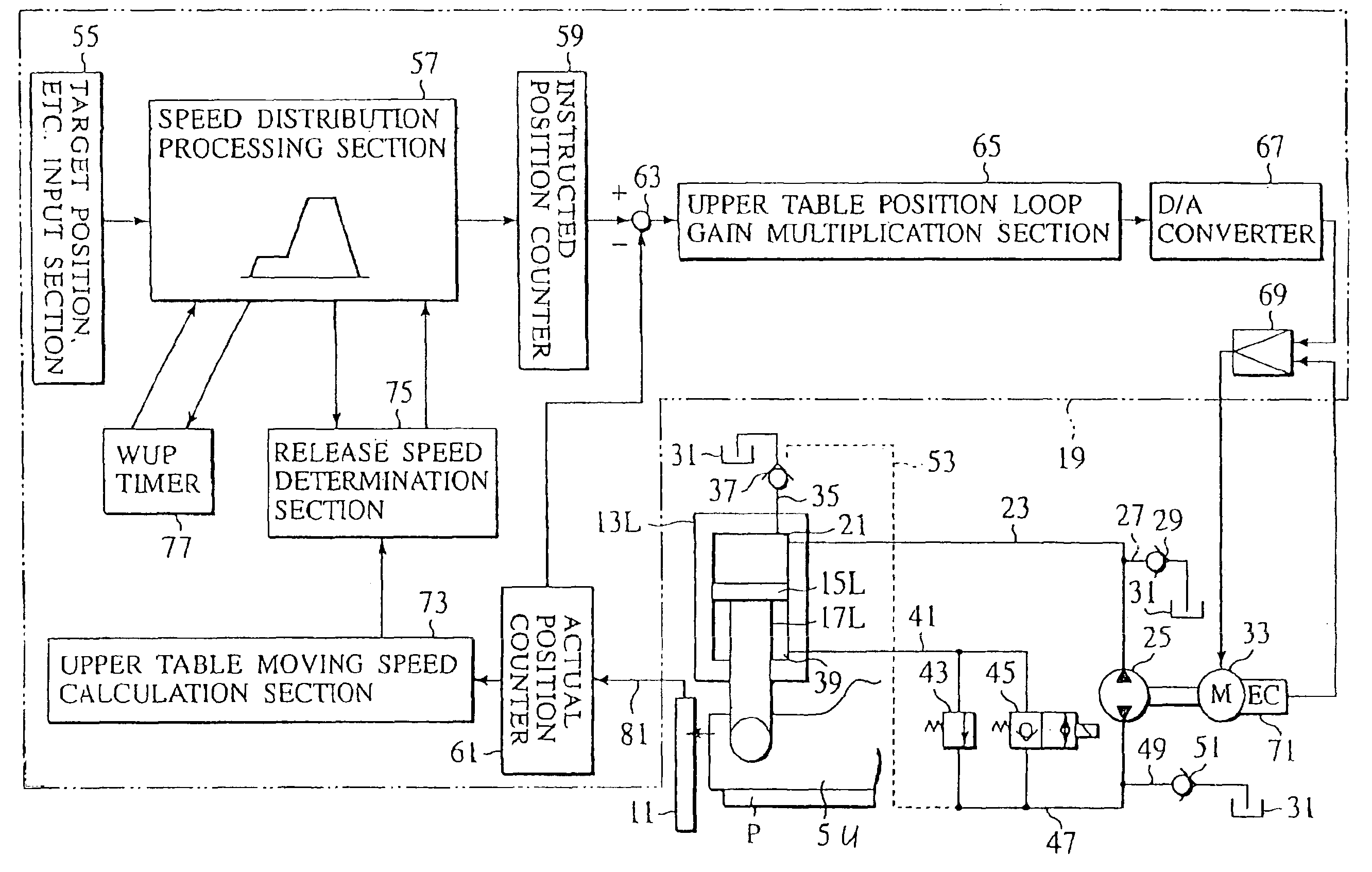
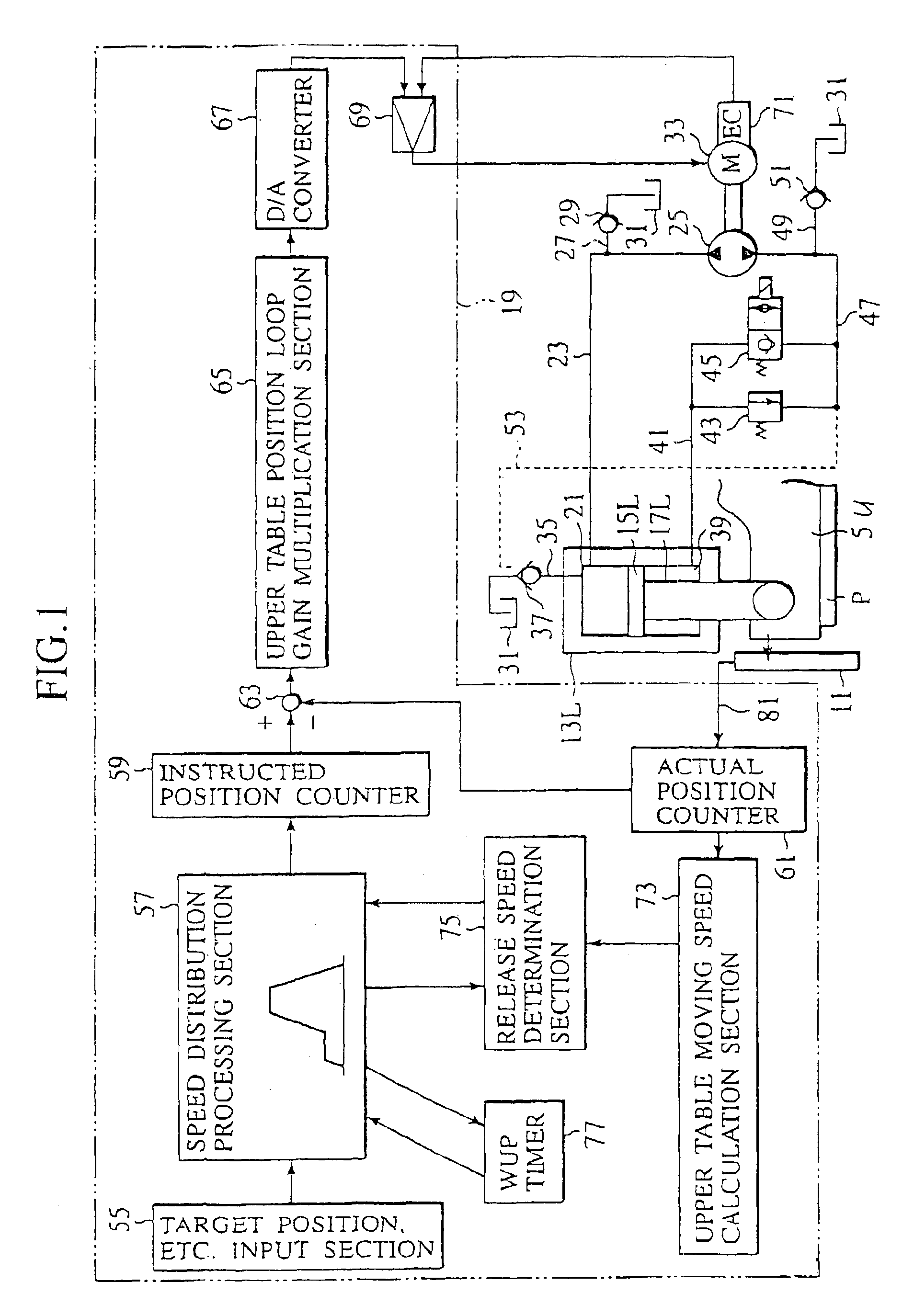
[0054]It is noted that a linear scale 11 which serves as a ram position detection means for measuring the height position of the upper table 5U is provided, so that the distance between the upper table 5U and the die D can be obtained us...


PUM

PropertyMeasurementUnit
Speedaaaaaaaaaa
Internal pressureaaaaaaaaaa

Abstract

If an instruction to move a ram (5U) is issued, a ram instructed speed is instructed to be suppressed to a certain warming-up speed not higher than a target speed until a release speed determination section (75) determines that a moving speed of the ram (5U) calculated by a ram moving speed calculation section (51) reaches a predetermined warming-up release speed; if the release speed determination section determines that the moving speed of the ram (5U) reaches the predetermined warming-up release speed, the warming-up speed is released to accelerate the ram (5U) to the target speed.

Description

TECHNICAL FIELD[0001]The present invention relates to a ram moving method in a hydraulic power unit which subjects a workpiece to pressing or the like by vertically moving a ram using a double acting cylinder which employs a two-way pump, a ram moving controller in the hydraulic power unit, a method for preventing a confinement phenomenon in an axial plunger pump, and the axial plunger pump, and more particularly relates to an axial plunger pump constituted to make a valve plate provided on an axial plunger pump, slightly rotatable.BACKGROUND ART[0002]In a hydraulic power unit which actuates a double acting cylinder using a two-way pump and thereby vertically moves a ram, the pressure of the double acting cylinder is in a negative pressure state when the cylinder starts moving the ram. Due to this, dead time occurs to the ram before actuating the two-way pump, supplying hydraulic oil to the double acting cylinder and moving the ram. Because of this ram dead time, a shock is generate...

Claims


Application Information

Patent Timeline
IPC IPC(8): B21D5/02B30B15/20B30B15/16F15B11/00F15B11/046F15B9/09F15B9/00F04B1/12F04B1/30F04B1/20
CPCB21D5/02B30B15/20F04B1/20F04B1/303F15B9/09F15B11/046F15B2211/20561F15B2211/27F15B2211/30505F15B2211/40515F15B2211/473F15B2211/50572F15B2211/526F15B2211/6336F15B2211/6346F15B2211/6651F15B2211/75
Inventor KANNO, KAZUHIROARIJI, NOBUAKI
Owner AMADA CO LTD
Why Eureka
Try Eureka