Method and apparatus for measuring polarization-mode dispersion

a technology of polarization-mode dispersion and optical devices, which is applied in the direction of measurement devices, instruments, structural/machine measurement, etc., can solve the problems of limited polarization-mode dispersion measurement accuracy of this technique, totally destroy the measured, and difficult to maintain a motionless condition

Inactive Publication Date: 2005-09-20
NAT RES COUNCIL OF CANADA
View PDF3 Cites 26 Cited by
  • Summary
  • Abstract
  • Description
  • Claims
  • Application Information

AI Technical Summary

Problems solved by technology

A major limitation of these methods is that any motion of the measuring apparatus, especially at the end of fibers, can totally destroy the measured results.
Maintaining a motionless condition is often difficult, especially with field measurements.
The polarization-mode dispersion measurement accuracy of this technique is limited by an additional PMD added by the measuring fiber i

Method used


Image

  • Method and apparatus for measuring polarization-mode dispersion
  • Method and apparatus for measuring polarization-mode dispersion
  • Method and apparatus for measuring polarization-mode dispersion

Examples


Embodiment Construction

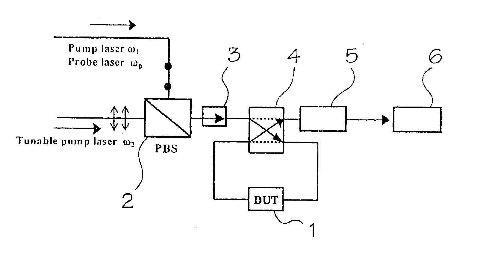
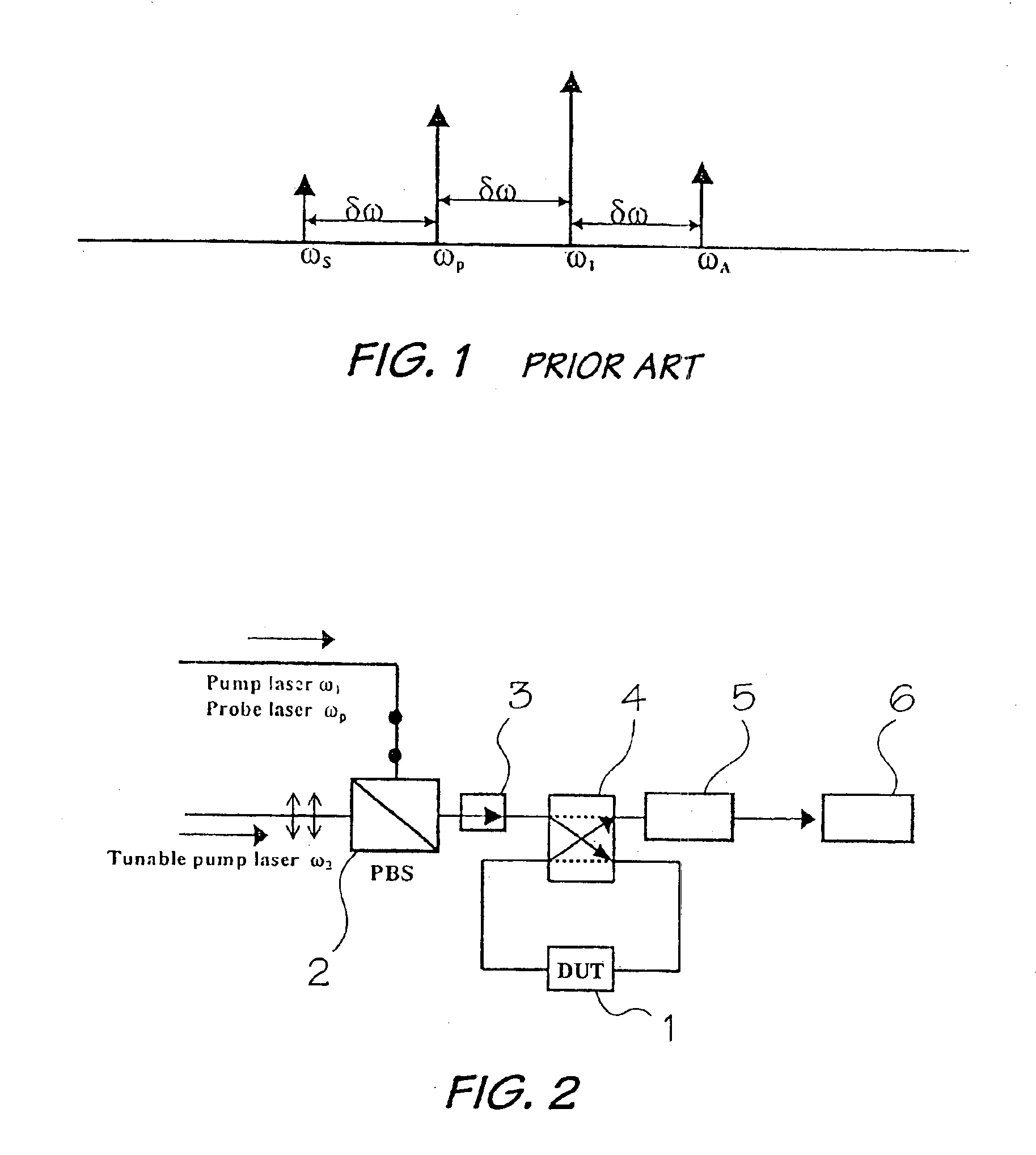
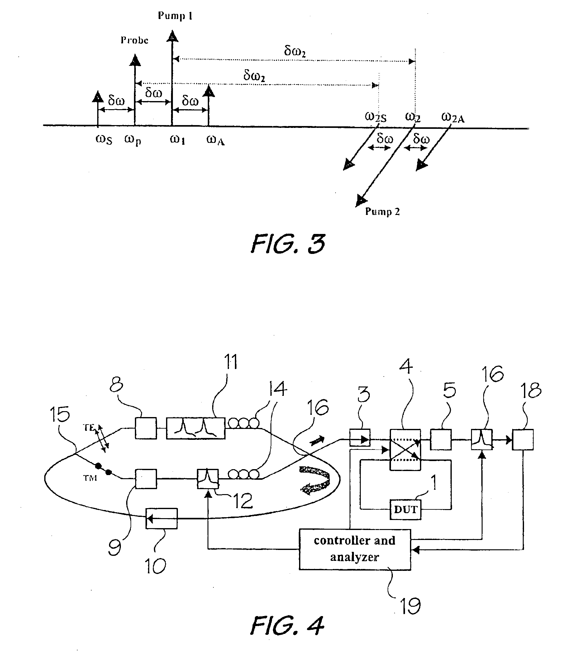
[0029]In a nonlinear optical material, wave-mixing arises from a nonlinear optical response when more than one wave (signal and pump) is present. The outcome of this effect is generation of another wave with an amplitude proportional to the product of the signal and the pump amplitudes. The phase and the frequency of the generated waves are the sum and difference of those of the interacting waves. FIG. 1 shows a traditional schematic of an optical spectrum generated by four-wave mixing in a semiconductor optical amplifier based on using two co-polarized laser beams. In this scheme the amplitude and the optical signal-to-noise ratio of the FWM products decrease quickly with increasing frequency shift between the pump and the probe signal frequencies [see A. Uskov et al, IEEE J. Quantum Electron 30, 1769-1781 (1994)]. In this case, there is described a broad-band orthogonal-pump (BOP) scheme based on using two orthogonally polarized pumps which give constant amplitude and optical sign...


PUM


Abstract

Polarization-mode dispersion (PMD) of an optical device, i.e. fiber or component is effected by launching a first pump laser beam of a fixed wavelength, a probe laser beam with a second fixed wavelength and a second pump laser beam having a variable wavelength and a polarization direction orthogonal to the other two beams into an optical device to generate three output signals which are input into a semiconductor optical amplifier to generate four-wave mixing (FWM) products. The average PMD of the device is computed by measuring the power of the FWM products versus the wavelength of the second pump laser beam.

Description

BACKGROUND OF THE INVENTION[0001]1. Field of the Invention[0002]This invention relates to a method and apparatus for measuring polarization-mode dispersion in optical devices such as optical fibers or components.[0003]2. Discussion of the Prior Art[0004]Polarization-mode dipersion (PMD) is a fundamental property of optical fiber and components by which any lightwave signal is split into two polarization modes that travel at different speeds on the basis of polarization state. The two polarization modes experience a difference in propagation time known as differential group delay (DGD). The PMD of an optical fiber or component is simply the average DGD. Existing PMD, measuring techniques [see, for example Y. Namihira et al, Electron Lett., 1992, 28, No. 25, 2265-2266 (1992) and A. Galtarossa et al, J. of Lighwave Technol., 14, 42-42 (1996)] utilize the fixed-analyzer method, the Jones-matrix method, and the Poincare-sphere method. A major limitation of these methods is that any motio...

Claims


Application Information

Patent Timeline
IPC IPC(8): G01N21/00G01M11/00
CPCG01M11/336
Inventor LU, ZHENGUOSUN, FENGGUOXIAO, GAOZHIGROVER, CHANDER P.
Owner NAT RES COUNCIL OF CANADA
Why Eureka
Try Eureka