
Solid state laser

a laser and solid state technology, applied in lasers, optical resonator shape and construction, active medium materials, etc., can solve the problems of not being able to achieve high pulse repetition rate, not only polarizing in a particular orientation, but also exhibiting anisotropy in light absorbing characteristics, etc., to achieve excellent pumping efficiency and distribution of pumping light, and easy alignment of crystal axes

Inactive Publication Date: 2005-09-20
ORC MFG
View PDF18 Cites 1 Cited by
  • Summary
  • Abstract
  • Description
  • Claims
  • Application Information

AI Technical Summary

Benefits of technology

The present invention provides a solid state laser with high pumping efficiency and uniform pumping of the laser medium. The laser medium is designed to face the pumping light source and the reflection portion, allowing for easy alignment of the crystal axis. The laser is simple and easy to use, and can provide high-quality laser oscillation. It is also efficient in using anisotropic laser media that have different performances in different directions.

Problems solved by technology

Nd:YAG crystals feature high mechanical strength and excellent thermal conductivity, but are not suitable for oscillation at high pulse repetition rate over 30 kHz because of longer fluorescent lifetime.
However, since Nb:YVO4 crystals have a single crystal axis, when used for laser oscillation, they not only oscillate in polarized in a particular orientation but also exhibit anisotropy in light absorbing characteristic.
Accordingly, any pumping light not absorbed by the solid state laser rod 1 passes through the gap for the cooling medium 2 and the cooling tube 3 for at least twice, thereby attenuating the pumping light and failing to effectively utilize the reflection light.
However, all of the above mentioned conventional LD-pumped solid state lasers have a common problem that the laser medium can not be uniformly pumped by the LD.
As a result, the beam quality may be deteriorated as mentioned in the following Reference Patent 5.
Other problems associated with the conventional solid state lasers include difficulty in aligning the crystal axis of the laser medium and incapability of uniformly and efficiently pumping the laser medium.
As a result, a part of the pumping light 82 passes through the output mirror 84, thereby not efficiently pumping the laser medium 81.

Method used


Image

  • Solid state laser
  • Solid state laser
  • Solid state laser

Examples


Embodiment Construction

[0040]Now, a presently preferred embodiment of the present invention will be described in detail by reference to the accompanying drawings.

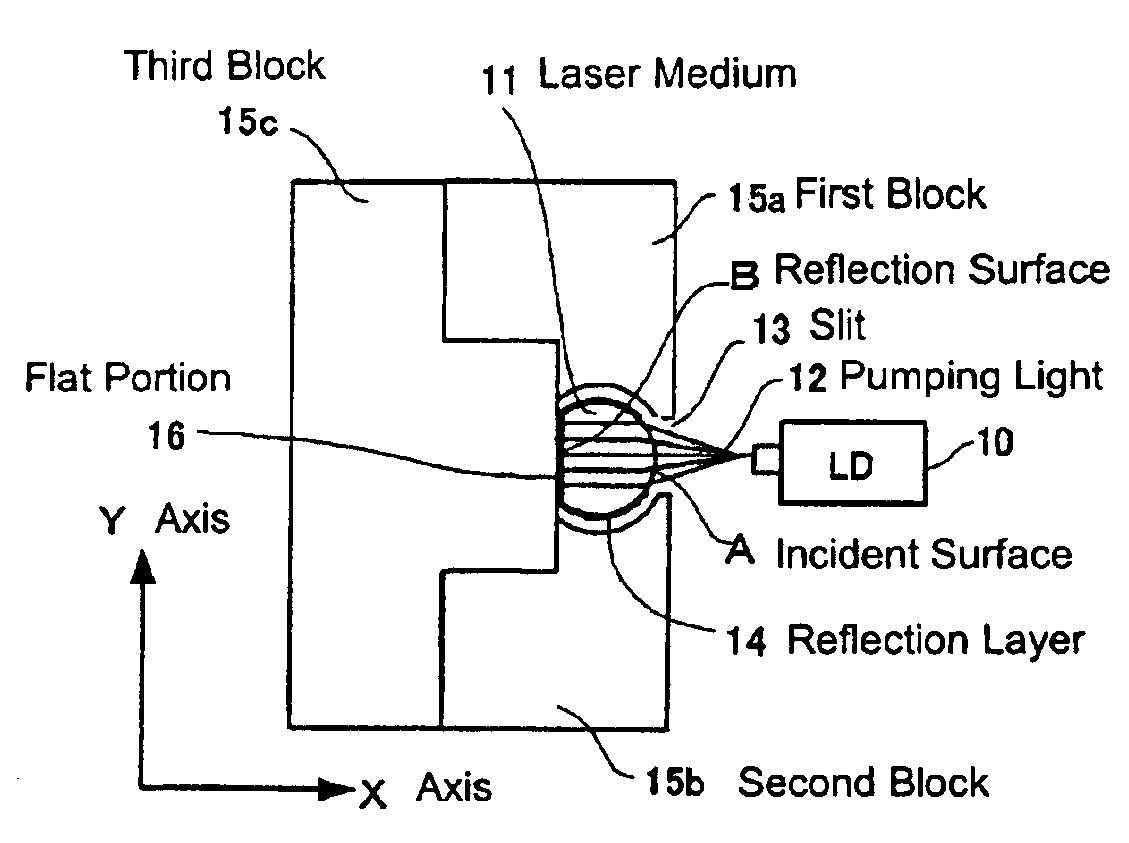
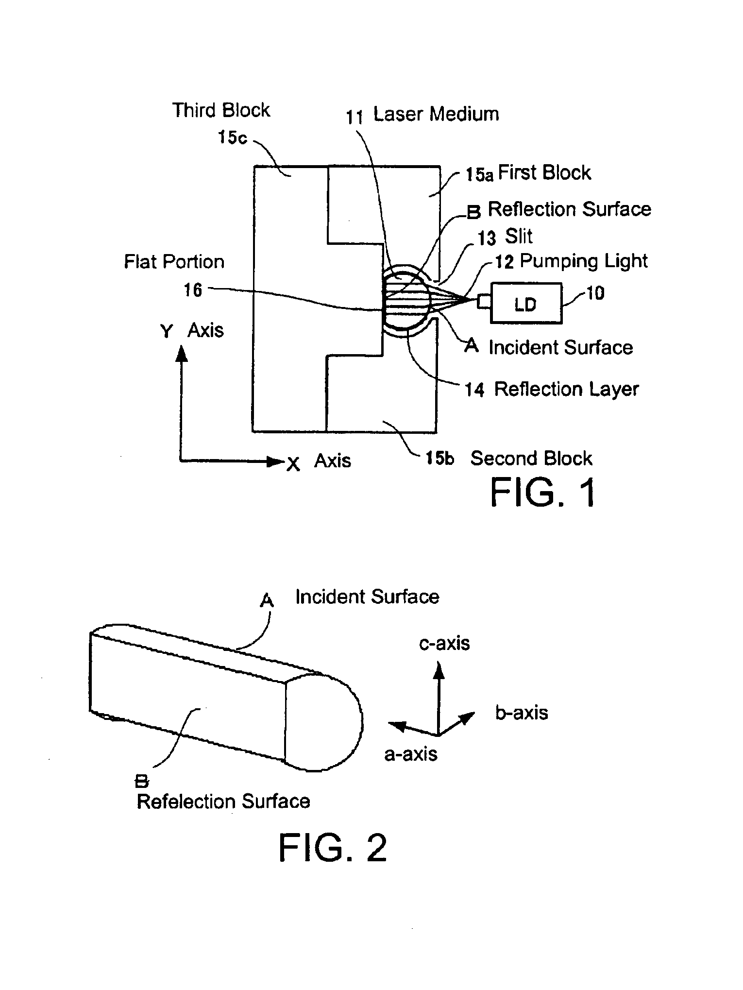
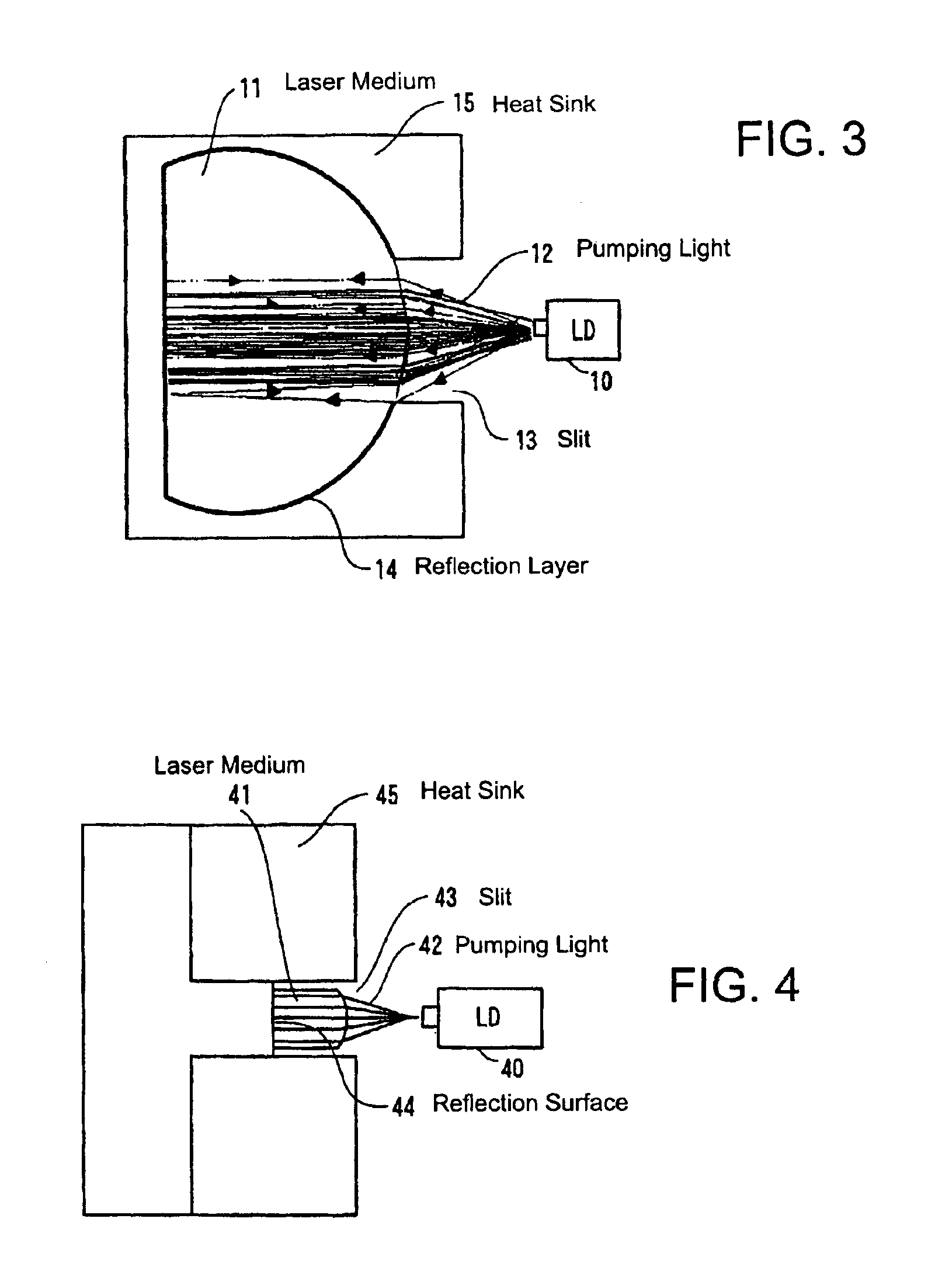
[0041]FIG. 1 is a cross section view of the LD-pumped solid state laser according to an embodiment of the present invention (referred to as the embodied solid state laser below) in the plane perpendicular to the direction of laser oscillation axis. FIG. 2 shows a perspective view of the laser medium to be used in the embodied solid state laser. FIG. 3 shows a trace of pumping light when the embodied solid state laser is pumped.

[0042]The embodied solid state laser comprises a LD 10, a laser medium 11 and a heat sink 15 comprising a first block 15a, second block 15b and a third block 15c.

[0043]The LD 10 used as the pumping light source 12 is 40 watts in output, 40 degrees in total diffusing angle (half-amplitude-width) and 800 nm in wavelength. Note that 1064 nm thick Ar coating and optical polishing are made on the laser oscillation edge surface ...


PUM


Abstract

The solid state laser comprises the laser medium 11 for absorbing the pumping light 12 from the LD 10 and generating or amplifying the light having a predetermined wavelength and a heat sink comprising the first block 15a, the second block 15b and the third block 15c for aligning the laser medium 11, cooling the laser medium 11 and reflecting the pumping light 12. The laser medium 11 has an arcuate light incident surface A and a flat reflection portion. The pumping light 12 having a diffusing angle is converted into parallel light by the light incident surface A, thereby pumping the laser medium 11 uniformly. The flat reflection portion makes it easy to align laser medium 11 having anisotropic characteristic and helps to efficiently pump the laser medium 11 by reflecting the reflection light substantially in parallel with the incident light.

Description

BACKGROUND OF THE INVENTION[0001]1. Field of the Invention[0002]The present invention relates generally to a solid state laser, more specifically to a solid state laser pumped by a laser diode (abbreviated as LD below) as a pumping light source. Such solid state laser is excellent in both pumping efficiency and pumping distribution as well as easy in aligning the crystal axis even in an anisotropic laser medium.[0003]2. Description of Related Art[0004]LD-pumped solid state lasers using a LD as a pumping light source attract considerable attention as compact, highly efficient and longer lifetime laser light sources as compared to lamp-pumped solid state lasers. In particular, performance and quality of a LD have been improved significantly in recent years, thereby accelerating practical applications of such LD-pumped all solid state lasers. Such all solid state semiconductor lasers extend lifetime to 10,000 hours as compared to 1,000 hours of conventional lamp-pumped semiconductor la...

Claims


Application Information

Patent Timeline
Patent Type & Authority Patents(United States)
IPC IPC(8): H01S3/09H01S3/091H01S3/16H01S3/092H01S3/0915H01S3/094H01S3/06H01S3/08H01S3/0941H01S3/04
CPCH01S3/0602H01S3/0941H01S3/0625H01S3/025H01S3/0405H01S3/042H01S3/061H01S3/094084
Inventor NUNOKAWA, HIROSHIAMANO, SATORU
Owner ORC MFG
Learn More