

Image processing method, apparatus, and storage medium
a technology of image processing and storage media, applied in the field of image processing methods and image processing apparatuses, can solve the problems of reducing the efficiency of memory use, requiring a lot of header information processors, etc., and achieve the effect of minimizing power consumption of the whole system and prolonging the total processing tim
- Summary
- Abstract
- Description
- Claims
- Application Information
AI Technical Summary
Benefits of technology
Problems solved by technology
Method used
Image

Examples
first embodiment
[First Embodiment]
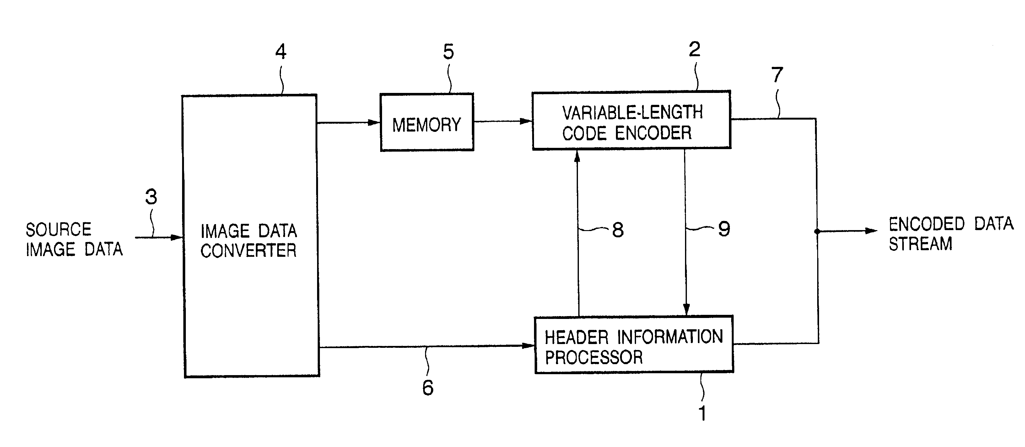
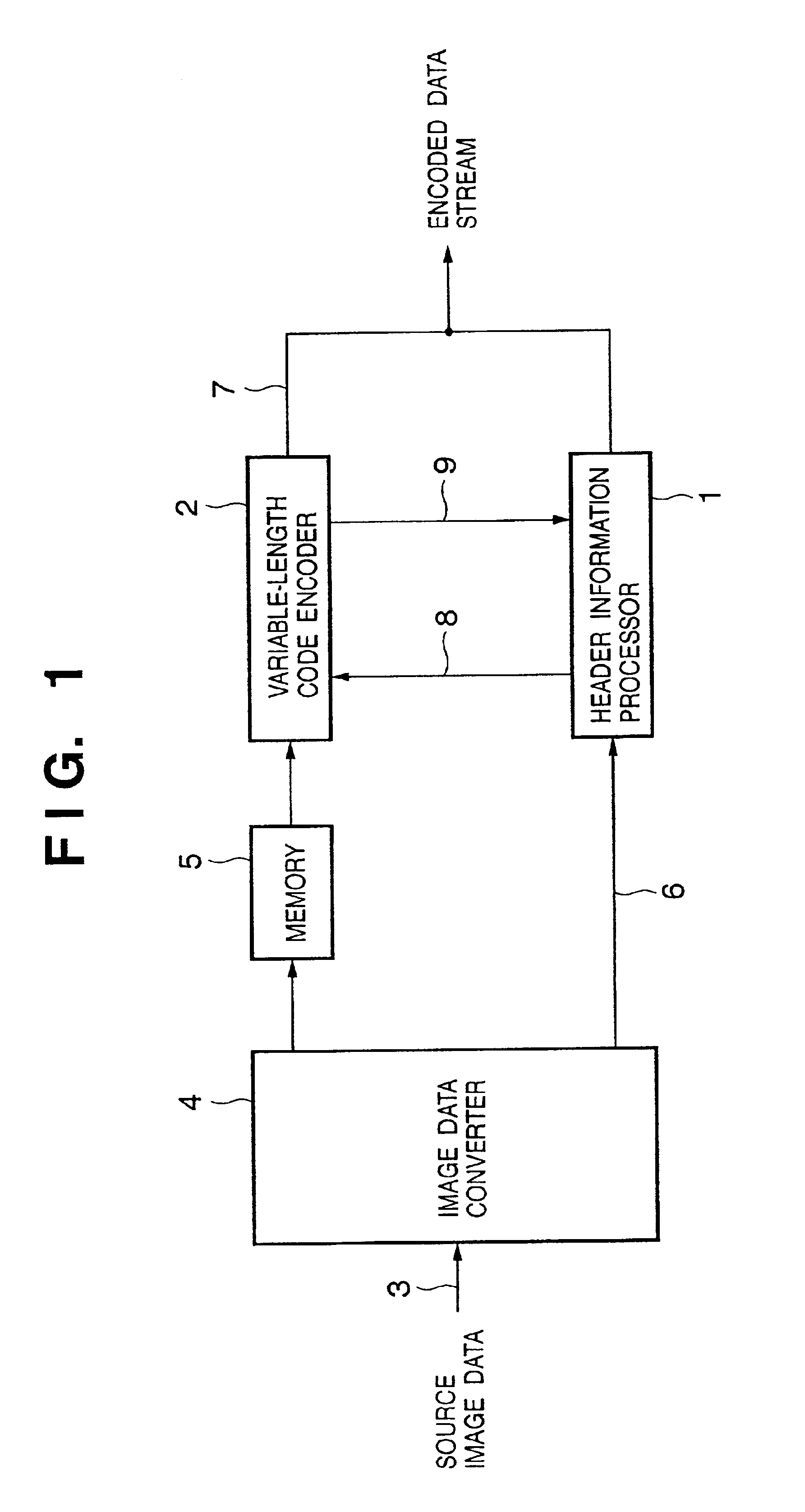
[0034]The first embodiment of the present invention will be described below with reference to the accompanying drawings. FIG. 1 is a functional block diagram showing an embodiment of an image encoding apparatus to which the present invention is applied. Referring to FIG. 1, reference numeral 1 denotes a header information processor; 2, a variable-length code encoder; 3, a source image data input signal; 4, an image data converter; 5, a memory; 6, an encoding parameter signal; 7, an encoded data stream output signal; 8, an operation start command signal; and 9, an operation end message signal.
[0035]Furthermore, FIG. 3 is a timing chart showing the operation sequence associated with the header information processor 1 and variable length code encoder 2 in the embodiment of the image encoding apparatus shown in FIG. 1. FIG. 5 is a flow chart showing the operation sequence. FIG. 11A is a flow chart showing an encoding process of the present invention. The operation mode...
second embodiment
[Second Embodiment]
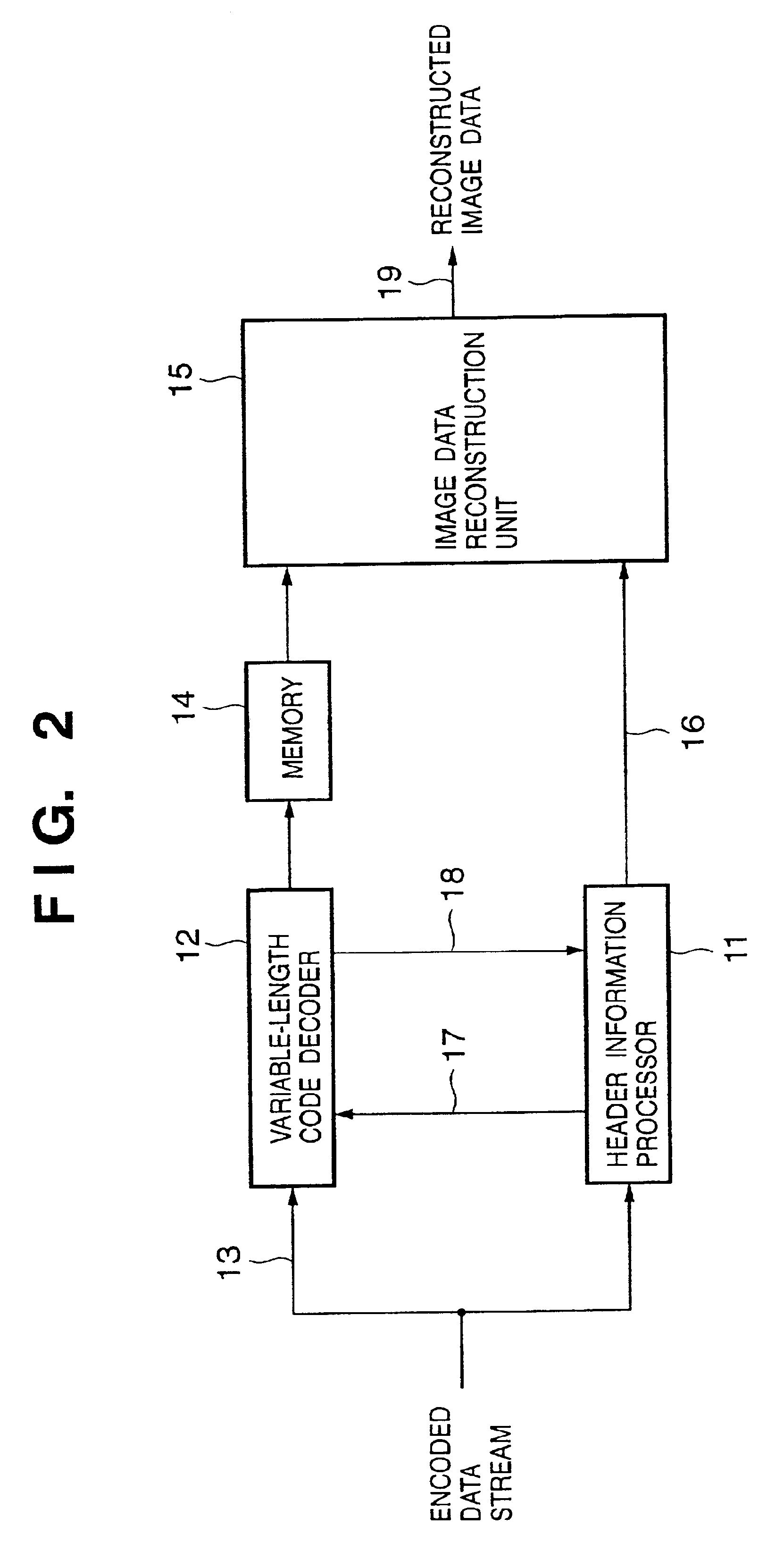
[0051]FIG. 2 is a functional block diagram of an image decoding apparatus according to the second embodiment of the present invention. Referring to FIG. 2, reference numeral 11 denotes a header information processor; 12, a variable-length code decoder; 13, an encoded data stream input signal; 14, a memory; 15, an image data reconstruction unit; 16, an encoding parameter signal; 17, an operation start command signal; 18, an operation end message signal; and 19, a reconstructed image data output signal. Furthermore, FIG. 3 is a timing chart showing the operation sequence associated with the header information processor 11 and variable-length code decoder 12 in the embodiment of the image decoding apparatus shown in FIG. 2. FIG. 11B is a flow chart showing the decoding process of the present invention.
[0052]The operation mode in the embodiment of the image decoding apparatus and, mainly, a series of operations associated with the decompression decoding process, espec...
third embodiment
[Third Embodiment]
[0072]The third embodiment of the present invention will be described below with reference to the accompanying drawings. FIG. 6 is a functional block diagram showing an embodiment of an image encoding apparatus to which the present invention is applied. Referring to FIG. 6, reference numeral 101 denotes a header information processor which operates according to program descriptions and comprises a versatile microprocessor; 102, a variable-length code encoder; 103, a source image data input signal; 104, an image data converter; 105, a memory; 106, an encoding parameter signal; 107, an encoded data stream output signal; 108, an operation start command signal; 109, an operation end message signal; 110, a memory; 111, an address signal output from the variable-length code encoder 102 to the memory 110; 112, an address signal output from the header information processor 101 to the memory 110; 113, a write data signal line to the memory 110; 114, a control signal line to...
PUM
 Abstract
Description
Claims
Application Information