Method and apparatus for selective caching of transactions in a computer system

a computer system and transaction processing technology, applied in the field of digital data processing, can solve the problems of imposing additional workload on the cpu, affecting system performance, and complex computer system, and achieve the effect of reducing the performance burden of write operations to the journal

Inactive Publication Date: 2005-09-20
IBM CORP
View PDF5 Cites 27 Cited by
  • Summary
  • Abstract
  • Description
  • Claims
  • Application Information

AI Technical Summary

Benefits of technology

[0012]A database manager selectively caches journal entries for certain database changes based on dynamic selection criteria. At least one of the selection criteria relates to the current level of performance of the system or some component thereof.

Problems solved by technology

A computer system is a very complex machine having numerous components which interact with each other.
While the CPU is the driving engine, the overall speed, or throughput, of the system can be affected by various other components, which either cause the CPU to wait or impose additional workload on the CPU. E.g., where the CPU needs data from memory, it may have to wait several cycles to access memory.
These operations, although they do not necessarily cause the CPU to be idle, impose additional workload on the CPU which can affect system performance.
They also introduce delay which may cause a human interacting with a computer to wait longer for a response.
Because the database is usually very large, it is generally impractical to keep the entire database, or even a major portion of it, in main memory at all times. Therefore a database application is usually characterized by a large number of storage access operations, most of which individually are small, and which are scattered among the storage addresses of the system.
Unfortunately, sequential writing means that the data in the journal is not organized according to the organizational structure of the database.
The journal e

Method used


Image

  • Method and apparatus for selective caching of transactions in a computer system
  • Method and apparatus for selective caching of transactions in a computer system
  • Method and apparatus for selective caching of transactions in a computer system

Examples


Embodiment Construction

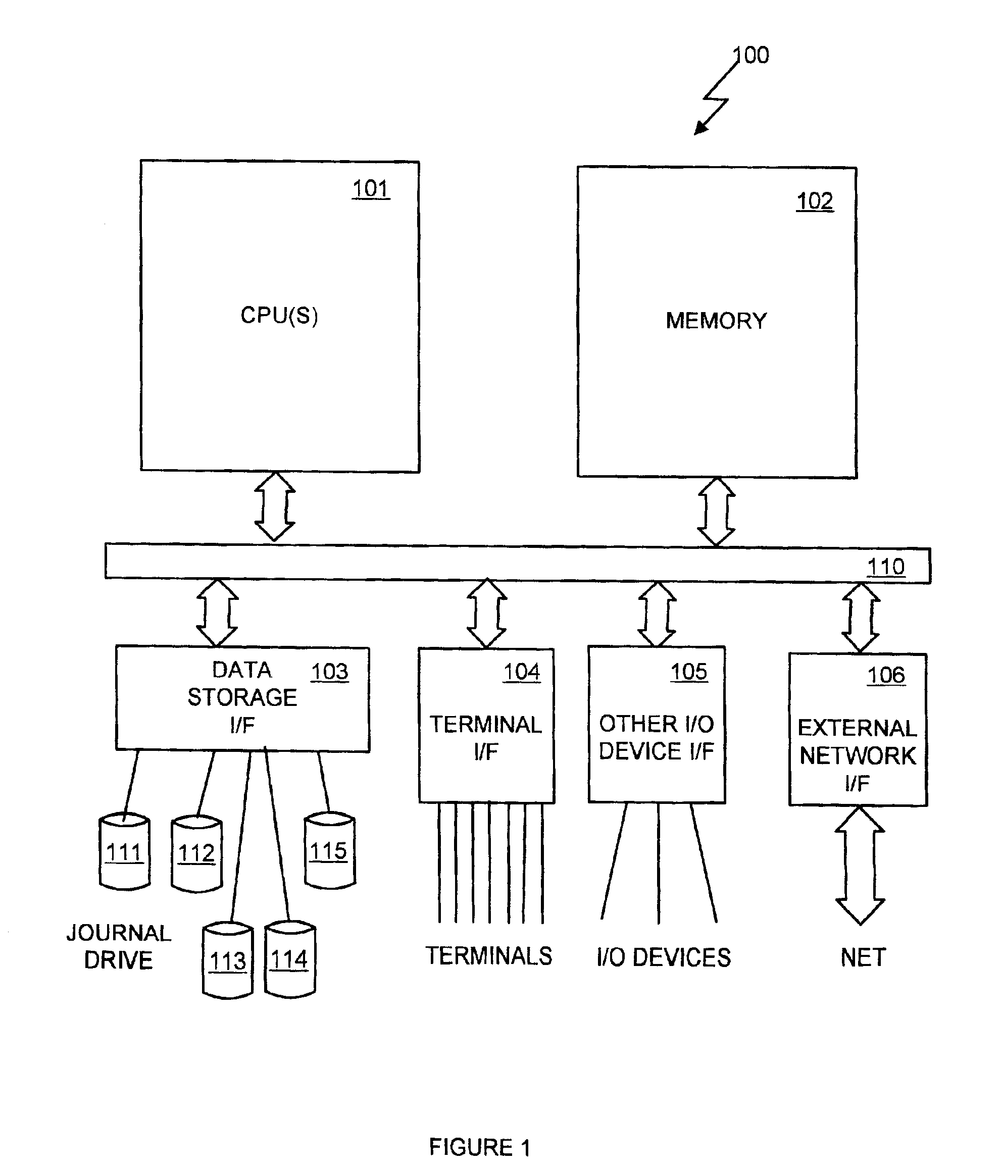
[0023]Referring to the Drawing, wherein like numbers denote like parts throughout the several views, FIG. 1 shows a high-level block diagram of a computer system 100 acting as a repository of database information, consistent with the preferred embodiment. Computer system 100 comprises one or more central processing unit (CPUs) 101, main memory 102, data storage interface 103, terminal interface 104, I / O device interface 105, and external network interface 106. The various devices communicate with each other via internal communications bus 110. CPU 101 is a general-purpose programmable processor, executing instructions stored in memory 102; while a single CPU is shown in FIG. 1, it should be understood that computer systems having multiple CPUs could be used. Memory 102 is a random-access volatile memory for storing data and programs; memory is shown conceptually as a single monolithic entity, it being understood that memory is often arranged in a hierarchy of caches and other memory...


PUM


Abstract

A database manager selectively caches journal entries for certain database changes based on dynamic selection criteria. Preferably, a journal disk drive is provided for storing changes to the database. Database change entries are sequentially cached in a main memory journal buffer, awaiting journal write. When a buffer is filled, its buffer contents are written to the journal disk. However, certain change operations will cause the contents of the buffer to be written to the journal disk immediately, before filling the buffer. Certain database change entries selectively cause the buffer to be written, depending on dynamic selection criteria. Preferably, these selection criteria take into account both the estimated time to recover in the event of a system crash and the current level of activity on the system. Generally, the busier the system, the more data will be cached, and vice versa.

Description

FIELD OF THE INVENTION[0001]The present invention relates generally to digital data processing, and more particularly to database management in a digital computer system.BACKGROUND OF THE INVENTION[0002]A modem computer system typically comprises a central processing unit (CPU) and supporting hardware necessary to store, retrieve and transfer information, such as communications busses and memory. It also includes hardware necessary to communicate with the outside world, such as input / output controllers or storage controllers, and devices attached thereto such as keyboards, monitors, tape drives, disk drives, communication lines coupled to a network, etc. The CPU is the heart of the system. It executes the instructions which comprise a computer program and directs the operation of the other system components.[0003]From the standpoint of the computer's hardware, most systems operate in fundamentally the same manner. Processors are capable of performing a limited set of very simple ope...

Claims


Application Information

Patent Timeline
IPC IPC(8): G06F17/30G06F12/00
CPCG06F17/30368G06F16/2358
Inventor OLSTAD, CHAD ALLENRICARD, GARY ROSSSTALLMAN, ADAM THOMASYOUNGREN, LARRY WILLIAM
Owner IBM CORP
Why Eureka
Try Eureka