
DRAM device and refresh control method therefor

a dynamic random access memory and control method technology, applied in the field of dram (dynamic random access memory) devices and refresh control methods, can solve the problems of high-capacity memory demand, power consumption, and high cost of srams for use as memories, and achieve the effect of reducing power consumption and efficient operation

Inactive Publication Date: 2005-09-20
LENOVO INNOVATIONS LTD HONG KONG
View PDF6 Cites 38 Cited by
  • Summary
  • Abstract
  • Description
  • Claims
  • Application Information

AI Technical Summary

Benefits of technology

[0010]Accordingly, it is an object of the invention to provide a DRAM device and a refresh control method therefor which can perform the control of self-refresh of DRAM without the necessity of taking the status of the device and the like into consideration and can reduce power consumption.
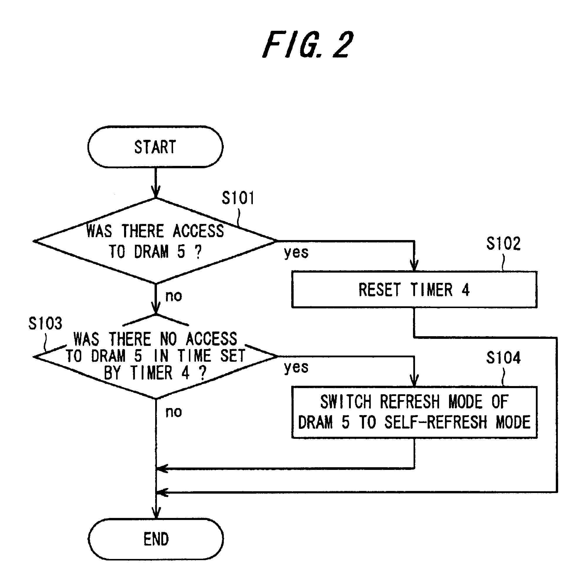
[0012]According to this construction, when there is no access to DRAM within the time set in a timer, the refresh mode of DRAM is switched to self-refresh mode. In this case, DRAM is automatically switched to self-refresh mode, not only in the case of particular conditions as in the prior art technique (when the refresh mode of DRAM is switched from auto-refresh to self-refresh within the routine) but also, for example, in the case where loop processing is carried out for a long period of time in such a state that data region on DRAM is stored in cache or buffer. Therefore, in the preparation of a software, this construction can eliminate the need to take the status of access to DRAM during the operation of the device into consideration. Further, the power consumption of DRAM during no access to DRAM can be suppressed.
[0014]According to this method, when no access to DRAM within a predetermined time has been detected, the refresh mode of DRAM is switched from ordinary refresh to self-refresh. When there is access to DRAM during the execution of self-refresh, the self-refresh is switched to the ordinary refresh. Therefore, the refresh control of DRAM is efficiently carried out, and a person responsible for the preparation of a software is not required to take the status of access to DRAM during the operation of the device into consideration. In addition, a reduction in power consumption can be realized.

Problems solved by technology

In electronic equipment provided with CPU and a memory, however, the tendency toward the adoption of multifunction has led to enlargement of softwares which has in turn led to a demand for high-capacity memories.
In PDAs (personal digital assistants) and portable telephones (cellular phones), PHS (personal handyphone systems) and the like which operate using a cell as a power supply, due to the limitation of supply of power, SRAMs (static random access memories) having low power consumption have hitherto been used although these SRAMs are expensive for use as memories.
In this case, in personal computers and the like which are operated through an ac power supply, the contents of DRAM are if necessary stored in a hard disk, while, in portable telephones and the like, the use of DRAM instead of SRAM poses a problem of loss of data upon turn-off of the power supply, which problem does not occur in SRAM wherein data is stored even when the power is supply in turn-off state.
Therefore, when a person responsible for the preparation of the software prepares the software without properly understanding the behavior of the software on the device, for example, occurrence of interruption and the status of transition of task, a problem occurs such that, despite the fact that DRAM is operated in self-refresh mode, a software, which enables access to this DRAM, is incorporated.
Another problem is as follows.
At that time, data on return address is lost by the self-refresh, and this makes it impossible to continue processing.
This, however, complicates the construction and processing, leading to an increase in cost.
This is making it difficult to perform switching of refresh mode while controlling the status of the hardware.

Method used


Image

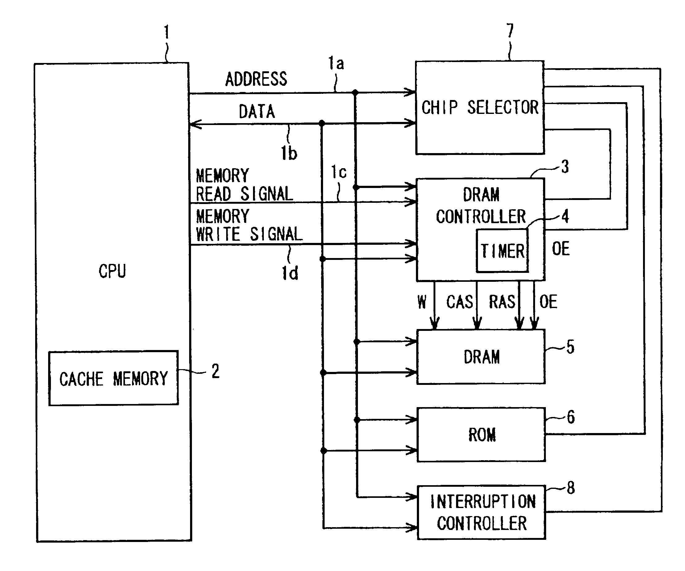
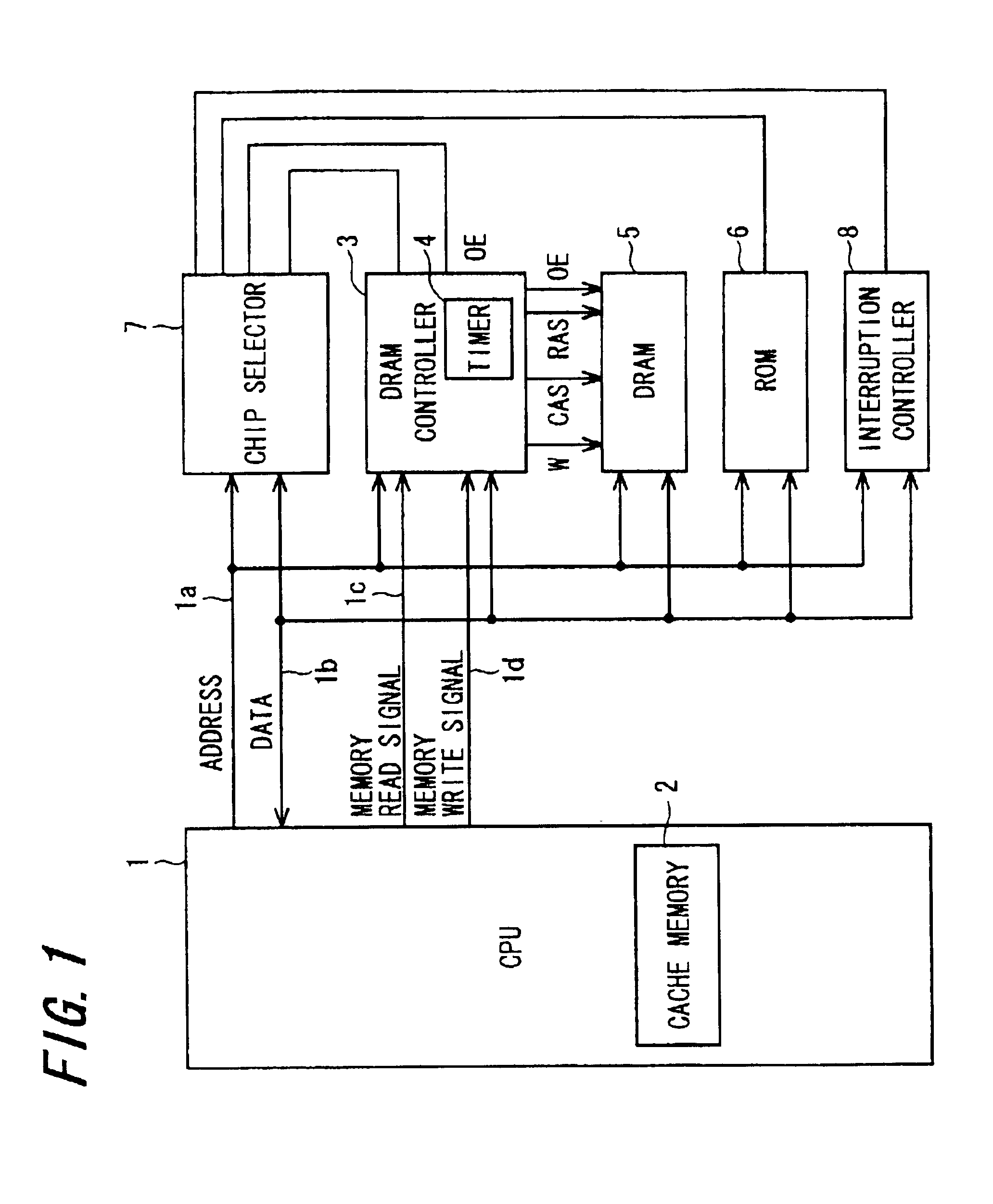
  • DRAM device and refresh control method therefor
  • DRAM device and refresh control method therefor
  • DRAM device and refresh control method therefor

Examples


Embodiment Construction

[0027]Preferred embodiments of the invention will be explained in conjunction with the accompanying drawings.

[0028][First Preferred Embodiment]

[0029]FIG. 1 shows a first preferred embodiment of the DRAM device according to the invention.

[0030]A DRAM controller 3, DRAM 5 with a built-in timer 4, ROM 6 for storing a program, a chip selector 7, and an interruption controller 8 are connected through an address bus 1a and a data bus 1b to CPU 1, with a built-in cache memory 2, which controls the whole device. A memory read signal 1c and a memory write signal 1d are applied at a predetermined time from CPU 1 to the DRAM controller 3. In the drawing, RAS is an abbreviation for row address strobe and is a control signal for transferring address bits for rows through the address bus 1a to DRAM 5. CAS is an abbreviation for column address strobe and is a control signal for transferring address bits for columns to DRAM 5. Further, OE represents an output enable signal.

[0031]CPU 1 executes vari...


PUM


Abstract

A DRAM (dynamic random access memory) device has: DRAM with a self-refresh function; a DRAM controller for controlling the DRAM; a timer built in or externally connected to the DRAM controller; and CPU for controlling the whole device. In the DRAM device, the DRAM controller monitors access from the CPU to the DRAM and, when there is no access to the DRAM within the time set in the timer, the DRAM controller switches a refresh mode to the self-refresh mode.

Description

FIELD OF THE INVENTION[0001]The invention relates to a DRAM (dynamic random access memory) device and a refresh control method for said DRAM device and more particularly to a DRAM device which can perform refresh in a DRAM device having a self-refresh function without the consideration of the status of the operation of the DRAM device and, at the same time, can realize a reduction in power consumption, and a refresh control method for said DRAM device.BACKGROUND OF THE INVENTION[0002]In DRAM, since the capacitor of a memory cell is in a floated state, accumulated charges are gradually lost by a pn junction leak and leak of current across drain and source of a transistor in a memory cell. In order to prevent this unfavorable phenomenon, refresh operation is carried out. That is, even when there is no request for reading or writing, information is periodically read and rewritten. This DRAM is suitable for an increase in capacitance and, thus, together with CPU, has been widely used in...

Claims


Application Information

Patent Timeline
IPC IPC(8): G11C11/406G06F12/16G06F12/00
CPCG11C11/406
Inventor YANO, MASATOSHI
Owner LENOVO INNOVATIONS LTD HONG KONG
Learn More